MC33389
Freescale Semiconductor, Inc.
DEVICE DESCRIPTION
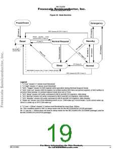
SBC MODES
be taken into account by the SBC (except for the go to
In normal mode the SBC get the watchdog word from the
microcontroller via SPI. In case of a trigger time failure (no
trigger or trigger outside the enable window) the SBC-reset is
switched to active.
Emergency mode).
Correspondence between SBC and CAN Transceiver Modes
The table here below gives the different possible CAN
transceiver modes versus SBC modes.
NormalRequest, Sleep And Emergency Mode
Watchdog is not active in this modes.
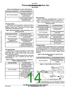
Table 14. CAN Modes Versus SBC Modes
When SBC Is In The
Following Mode
CAN Transceiver
Can Be In
Reset condition
NormalRequest
Normal
Bus Standby mode
Bus Standby mode
RXTX or RXOnly or BusStandby
Bus Standby
Standby
Sleep
Bus Standby
Emergency
Bus Standby
Normal & V2 off (over load)
(note)
Bus standby
Note: In case V2 is turned off either by SPI command
(standby mode) or by the SBC itself due to V2 over load
condition (V2 short to gnd or V2 over temperature) the CAN is
automatically set into the Bus standby mode and does not
return to TXRX mode automatically when V2 is back to 5V.
The CAN must be re configured to TXRX or RXonly mode
after a V2 turn off.
Watchdog
General
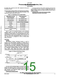
The software window watchdog function is used to
monitors the microcontroller operation in Normal and in
Standby modes. The window watchdog timing is derived from
the SBC-clock. The desired watchdog timing must be first
transmitted during the SBC configuration, in NormalRequest
mode, via SPI to SWCR register. It can also be changed later
on. Selectable watchdog timings are 5ms, 10ms, 20ms,
33ms, 50ms, 75ms, 100ms and 200ms. These timings
correspond to the full disable window plus full enable window.
Figure 15. Window Watchdog Timing
earliest trigger time
watchdog trigger
50%
50%
latest
trigger
time
SBC watchdog window
enable window
disabled window
nom. trigger period
latest
reset
time
Watchdog Timing
SBC-Reset OUT
time out
As soon as the watchdog trigger is received in the enable
window, the internal counter is reset and start a new disable
window. The SBC triggers the watchdog word at CSB low to
high transition. Any watchdog trigger outside the enable
window leads to SBC reset.
In Normal and Standby Modes
For More Information On This Product,
Go to: www.freescale.com
MC33389
MOTOROLA
15

 MOTOROLA [ MOTOROLA ]