MC33389
Freescale Semiconductor, Inc.
DEVICE DESCRIPTION
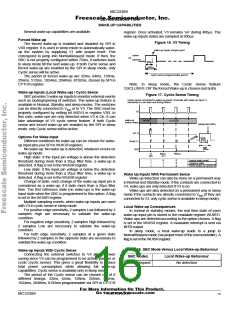
In the event of a permanent dominant TX state (for more
Full transmitting and receiving capabilities are enabled.
than 2ms) the output drivers are disabled. That assures the
operation of the complete system in case of a permanent
dominant TX state of one control unit. A defect control unit
autonomous go to RXOnly or TermVCC mode.
Full failure detection is enabled.
Note: Standard/RXTX and Extended/RXTX are equivalent.
RXOnly mode
The transmitter is disabled but the receive part of the
transceiver remains active. In this mode, RX reports bus and
TX activity (RX = TX or Bus dominant).
Low Power Modes
The transceiver provides a low power modes which can be
entered and exit by a SPI command. This is the BusStandby
mode with the lowest power consumption (for the
transceiver). CANL is biassed to the battery voltage via the
RTL output and the pull-up current source on CANL and pull-
down current source on CANH are disabled. Wake-up
requests are recognized by the transceiver, when a dominant
state is detected on either bus lines (Bus wake-up). On a Bus
wake-up request the SBC will activate the INTB output or, if it
is in sleep mode, switch to NormalRequest mode. This event
is stored in the WUISR status register.
Note: Standard/RXOnly and Extended/RXOnly are equivalent.
BusStandby Mode
This is the low power mode for the CAN transceiver. The
driver and receivers are disabled. Wake-up capability on both
bus lines as well as failure 3, 4, 7, 8 detection are enabled. In
bus standby mode RTL termination is set to Vbat
.
Global Power Save Concept
The SBC allows to minimize power consumption of the
ECU. Several operating modes are available to go to low
power consumption when the full activity is not required.
Several possibilities are provided to wake-up the ECU. This
allows to have peripherals or the microcontroller switched off
when no activity on the ECU is required.
To prevent false wake-up due to transients or RF fields,
wake-up threshold levels have to be maintained for a certain
time. In the transceiver low power mode, failure detection
circuit remains partly active to prevent increased power
consumption in cases of error 3, 4,7 and 8.
Two switchable independent supply voltages (V1 and V2)
are provided for optimum ECU power management.
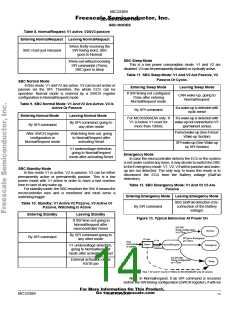
Power On
After the Vbat supply is switched on, the SBC is in
NormalRequest mode. The corresponding mode for the CAN
transceiver is BusStandby.
Generalities
The SBC can be operated in four modes: Sleep, Standby,
Normal and Emergency mode. After reset, the MC33389 is
automatically initialised to a temporally mode, NormalRequest,
Waiting for microcontroller configuration.
The CAN transceiver is supplied by V2. As long as V2 is
below its undervoltage threshold, the transceiver is forced to
BusStandby mode (fail safe property).
Reset Mode
Protection
This mode is entered after SBC power up, or if an incorrect
Software W/D trigger occurs. The minimum duration for reset
mode is 1ms typical, and unless a V1 failure condition, the
SBC enters the NormalRequest mode after reset.
In case of V1 failure condition leading to V1 low (ex: short
to gnd), the SBC goes in reset mode. If V1 is still below reset
threshold after 100ms, the behavior depends upon the device
version A, C or D:
A current limiting circuit protects the transmitter output
stages against short-circuit to positive and negative battery
voltage. If the junction temperature exceeds a maximum
value, the transmitter output stages are disabled. Because the
transmitter is responsible for a part of the power dissipation,
this will result in a reduced power dissipation and hence a
lower chip temperature. All other parts of the transceiver will
remain operating. The CANH and CANL inputs are protected
against electrical transients which may occur in an automotive
environment.
- A version : will enter sleep mode.
- C and D versions: will stay in reset mode.
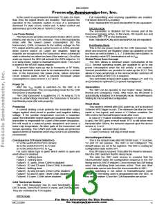
NormalRequest Mode
Consequence Of Failure Detections
S1 is the switch from RTH to Ground
S2 is the switch from RTL to V2 and
S3 is the switch from RTL to Vbat
This is the default mode after MC33389 reset. V1 is active,
V2 and V3 are passive. The SBC is not configured. The
default values are set in the registers. The SBC is waiting for
configuration data via the SPI.
For each failure type is given which switch is open and
which driver is disabled.
If no SPI data is received 75ms after the Reset is released,
then the SBC switches itself to sleep mode.
Failure 1 : nothing done
The data the SBC must receive to consider that the
microcontroller starts the configuration sequence is the SW
timing word (in SWCR register). Once received this SW timing
word, the watchdog timer becomes active. Then any other
control data can be sent from the microcontroller to SBC.
The watchdog is not active in NormalRequest mode
before the SW timing word is programmed into the SBC. In
this mode, neither V2 nor the CAN transmitter are active.
Failure 2 : nothing done
Failure3 : S1 open. Driver CANH is disabled
Failure4 : S2 and S3 open. Driver CANL is disabled
Failure5 : Nothing done
Failure6 : S2 and S3 open. Driver CANL disabled
Failure7: S2 and S3 open. Driver CANL disabled
Failure8: S1 open. CANH driver disabled
CAN Transceiver Modes
The CAN transceiver has its own functioning modes:
RXTX mode, TermVBAT/TermVCC mode, and RXOnly mode.
They are controlled by TCR register.
RXTX mode
For More Information On This Product,
Go to: www.freescale.com
MC33389
MOTOROLA
13

 MOTOROLA [ MOTOROLA ]