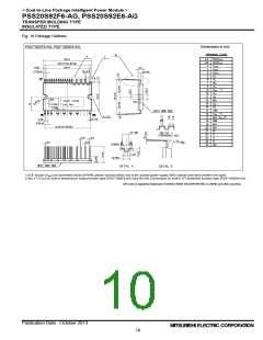
< Dual-In-Line Package Intelligent Power Module >
PSS20S92F6-AG, PSS20S92E6-AG
TRANSFER MOLDING TYPE
INSULATED TYPE
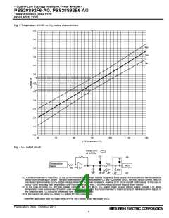
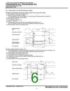
Fig. 5 Timing Charts of The DIPIPM Protective Functions
[A] Short-Circuit Protection (N-side only with the external shunt resistor and RC filter)
a1. Normal operation: IGBT ON and outputs current.
a2. Short circuit current detection (SC trigger)
(It is recommended to set RC time constant 1.5~2.0μs so that IGBT shut down within 2.0μs when SC.)
a3. All N-side IGBT's gates are hard interrupted.
a4. All N-side IGBTs turn OFF.
a5. FO outputs for tFo=minimum 20μs.
a6. Input = “L”: IGBT OFF
a7. Fo finishes output, but IGBTs don't turn on until inputting next ON signal (LH).
(IGBT of each phase can return to normal state by inputting ON signal to each phase.)
a8. Normal operation: IGBT ON and outputs current.
Lower-side control
input
a6
SET
RESET
Protection circuit state
Internal IGBT gate
a3
a4
SC trip current level
a1
a8
Output current Ic
a7
a2
SC reference voltage
Sense voltage of
the shunt resistor
Delay by RC filtering
Error output Fo
a5
[B] Under-Voltage Protection (N-side, UVD)
b1. Control supply voltage V D exceeds under voltage reset level (UVDr), but IGBT turns ON by next ON signal (LH).
(IGBT of each phase can return to normal state by inputting ON signal to each phase.)
b2. Normal operation: IGBT ON and outputs current.
b3. VD level drops to under voltage trip level. (UVDt).
b4. All N-side IGBTs turn OFF in spite of control input condition.
b5. Fo outputs for tFo=minimum 20μs, but output is extended during VD keeps below UVDr.
b6. VD level reaches UVDr.
b7. Normal operation: IGBT ON and outputs current.
Control input
RESET
RESET
b1
SET
Protection circuit state
UVDr
b6
Control supply voltage VD
UVDt
b3
b4
b7
b2
Output current Ic
Error output Fo
b5
Publication Date : October 2013
6

 MITSUBISHI [ Mitsubishi Group ]