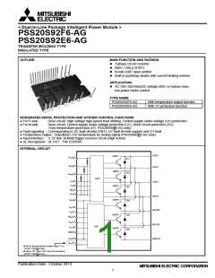
< Dual-In-Line Package Intelligent Power Module >
PSS20S92F6-AG, PSS20S92E6-AG
TRANSFER MOLDING TYPE
INSULATED TYPE
MAXIMUM RATINGS (Tj = 25°C, unless otherwise noted)
INVERTER PART
Symbol
VCC
Parameter
Supply voltage
Condition
Applied between P-NU,NV,NW
Applied between P-NU,NV,NW
Ratings
450
Unit
V
VCC(surge)
VCES
±IC
Supply voltage (surge)
500
V
Collector-emitter voltage
Each IGBT collector current
Each IGBT collector current (peak)
Collector dissipation
600
V
TC= 25°C
20
A
±ICP
TC= 25°C, less than 1ms
TC= 25°C, per 1 chip
40
A
PC
33.3
W
°C
Tj
Junction temperature
(Note 1)
-30~+150
Note1: The maximum junction temperature rating of built-in power chips is 150°C(@Tc≤100°C).However, to ensure safe operation of DIPIPM, the average
junction temperature should be limited to Tj(Ave)≤125°C (@Tc≤100°C).
CONTROL (PROTECTION) PART
Symbol
VD
Parameter
Control supply voltage
Control supply voltage
Input voltage
Condition
Applied between VP1-VNC, VN1-VNC
Applied between VUFB-U, VVFB-V, VWFB-W
Applied between UP, VP, WP-VPC, UN, VN, WN-VNC
Applied between FO-VNC
Ratings
20
Unit
V
VDB
VIN
VFO
IFO
20
V
-0.5~VD+0.5
-0.5~VD+0.5
1
V
Fault output supply voltage
Fault output current
V
Sink current at FO terminal
mA
V
VSC
Current sensing input voltage
Applied between CIN-VNC
-0.5~VD+0.5
TOTAL SYSTEM
Symbol
Parameter
Self protection supply voltage limit
(Short circuit protection capability)
Condition
VD = 13.5~16.5V, Inverter Part
Tj = 125°C, non-repetitive, less than 2μs
Ratings
400
Unit
V
VCC(PROT)
TC
Module case operation temperature
Storage temperature
Measurement point of Tc is provided in Fig.1
-30~+100
-40~+125
°C
°C
Tstg
60Hz, Sinusoidal, AC 1min, between connected all pins
and heat sink plate
Viso
Isolation voltage
1500
Vrms
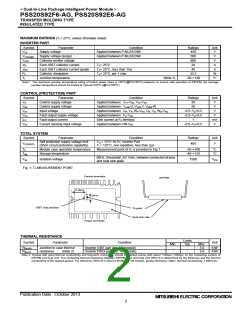
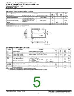
Fig. 1: TC MEASUREMENT POINT
Control terminals
DIPIPM
11.6mm
3mm
IGBT chip position
Tc point
Heat sink side
Power terminals
THERMAL RESISTANCE
Limits
Typ.
Symbol
Parameter
Condition
Unit
Min.
Max.
Rth(j-c)Q
Rth(j-c)F
Inverter IGBT part (per 1/6 module)
Inverter FWDi part (per 1/6 module)
-
-
-
-
3.0
3.9
K/W
K/W
Junction to case thermal
resistance
(Note 2)
Note 2: Grease with good thermal conductivity and long-term endurance should be applied evenly with about +100μm~+200μm on the contacting surface of
DIPIPM and heat sink. The contacting thermal resistance between DIPIPM case and heat sink Rth(c-f) is determined by the thickness and the thermal
conductivity of the applied grease. For reference, Rth(c-f) is about 0.3K/W (per 1/6 module, grease thickness: 20μm, thermal conductivity: 1.0W/m•K).
Publication Date : October 2013
2

 MITSUBISHI [ Mitsubishi Group ]