MITSUBISHI MICROCOMPUTERS
3827 Group
SINGLE-CHIP 8-BIT CMOS MICROCOMPUTER
PULSE WIDTH MODULATION (PWM)
The 3827 group has a PWM function with an 8-bit resolution,
based on a signal that is the clock input XIN or that clock input di-
vided by 2.
PWM Operation
When at least either bit 1 (PWM0 output enable bit) or bit 2 (PWM1
output enable bit) of the PWM control register is set to “1”, opera-
tion starts by initializing the PWM output circuit, and pulses are
output starting at an “H”. When one PWM output is enabled and
that the other PWM output is enabled, PWM output which is en-
abled to output later starts pulse output from halfway.
Data Setting
The PWM output pin also functions as ports P50 and P51. Set the
PWM period by the PWM prescaler, and set the period during
which the output pulse is an “H” by the PWM register.
If PWM count source is f(XIN) and the value in the PWM prescaler
is n and the value in the PWM register is m (where n = 0 to 255
and m = 0 to 255) :
When the PWM register or PWM prescaler is updated during
PWM output, the pulses will change in the cycle after the one in
which the change was made.
PWM period = 255 ✕ (n+1)/f(XIN)
= 51 ✕ (n+1) µs (when XIN = 5 MHz)
51 ✕ m ✕ (n+1)
µs
Output pulse “H” period = PWM period ✕ m/255
= 0.2 ✕ (n+1) ✕ m µs
255
(when XIN = 5 MHz)
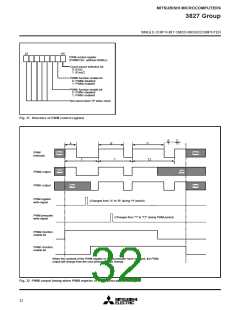
PWM output
T = [51 ✕ (n+1)] µs
m: Contents of PWM register
n : Contents of PWM prescaler
T : PWM cycle (when f(XIN) = 5 MHz)
Fig. 29 Timing of PWM cycle
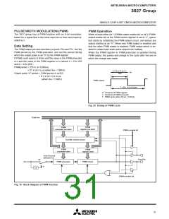
Data bus
PWM
register pre-latch
PWM
prescaler pre-latch
PWM1 enable bit
Transfer control circuit
PWM
prescaler latch
PWM
register latch
Count source
selection bit
Port P5
6
“0”
PWM circuit
XIN
PWM prescaler
“1”
1/2
PWM0 enable bit
Fig. 30 Block diagram of PWM function
31

 MITSUBISHI [ Mitsubishi Group ]