MITSUBISHI MICROCOMPUTERS
3827 Group
SINGLE-CHIP 8-BIT CMOS MICROCOMPUTER
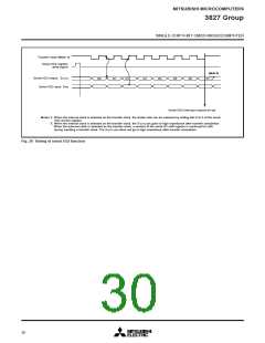
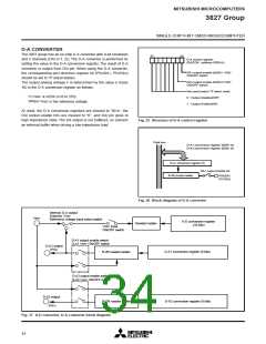
Transfer clock (Note 1)
Serial I/O2 register
write signal
(Note 2)
Serial I/O2 output SOUT2
Serial I/O2 input SIN2
D2
D0
D1
D3
D4
D5
D6
D7
Serial I/O2 interrupt request bit set
Notes 1: When the internal clock is selected as the transfer clock, the divide ratio can be selected by setting bits 0 to 2 of the serial
I/O2 control register.
2: When the internal clock is selected as the transfer clock, the SOUT2 pin goes to high impedance after transfer completion.
When the external clock is selected as the transfer clock, a content of the serial I/O shift register is continued to shift
during inputting a transfer clock. The SOUT2 pin does not go to high impedance after transfer completion.
Fig. 28 Timing of serial I/O2 function
30

 MITSUBISHI [ Mitsubishi Group ]