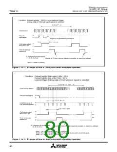
Mitsubishi microcomputers
M16C / 61 Group
SINGLE-CHIP 16-BIT CMOS MICROCOMPUTER
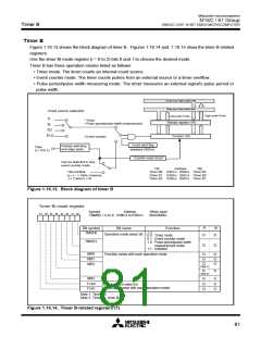
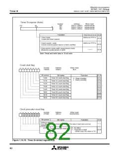
Timer B
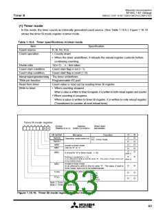
(2) Event counter mode
In this mode, the timer counts an external signal or an internal timer's overflow. (See Table 1.16.7.)
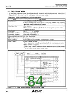
Figure 1.16.17 shows the timer Bi mode register in event counter mode.
Table 1.16.7. Timer specifications in event counter mode
Item
Specification
• External signals input to TBiIN pin
Count source
• Effective edge of count source can be a rising edge, a falling edge, or falling
and rising edges as selected by software
Count operation
• Counts down
• When the timer underflows, it reloads the reload register contents before
continuing counting
Divide ratio
1/(n+1)
n : Set value
Count start condition
Count stop condition
Count start flag is set (= 1)
Count start flag is reset (= 0)
Interrupt request generation timing The timer underflows
TBiIN pin function
Read from timer
Write to timer
Count source input
Count value can be read out by reading timer Bi register
• When counting stopped
When a value is written to timer Bi register, it is written to both reload register and counter
• When counting in progress
When a value is written to timer Bi register, it is written to only reload register
(Transferred to counter at next reload time)
Timer Bi mode register
b7 b6 b5 b4 b3 b2 b1 b0
Symbol
Address
When reset
00XX00002
TBiMR(i=0 to 2) 039B16 to 039D16
0
1
R
W
Bit symbol
Bit name
Function
b1 b0
TMOD0
TMOD1
MR0
Operation mode select bit
0 1 : Event counter mode
b3 b2
Count polarity select
bit (Note 1)
0 0 : Counts external signal's
falling edges
0 1 : Counts external signal's
rising edges
MR1
1 0 : Counts external signal's
falling and rising edges
1 1 : Inhibited
0 (Fixed to “0” in event counter mode; i = 0)
MR2
MR3
(Note 2)
(Note 3)
Nothing is assigned (i = 1, 2).
In an attempt to write to this bit, write “0” . The value, if read,
turns out to be indeterminate.
Invalid in event counter mode.
In an attempt to write to this bit, write “0” . The value, if read
in event counter mode, turns out to be indeterminate.
Invalid in event counter mode.
Can be “0” or “1”.
TCK0
TCK1
0 : Input from TBiIN pin (Note 4)
1 : TBj overflow
Event clock select
(j = i – 1; however, j = 2 when i = 0)
Note 1: Valid only when input from the TBiIN pin is selected as the event clock.
If timer's overflow is selected, this bit can be “0” or “1”.
Note 2: Timer B0.
Note 3: Timer B1, timer B2.
Note 4: Set the corresponding port direction register to “0”.
Figure 1.16.17. Timer Bi mode register in event counter mode
84

 MITSUBISHI [ Mitsubishi Group ]