Mitsubishi microcomputers
M16C / 61 Group
SINGLE-CHIP 16-BIT CMOS MICROCOMPUTER
Timer A
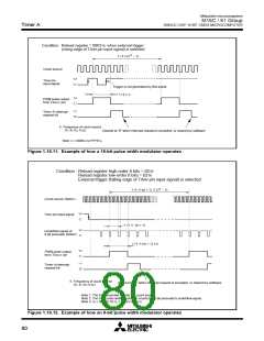
Condition : Reload register = 000316, when external trigger
(rising edge of TAiIN pin input signal) is selected
1 / fi X
(216 – 1)
Count source
“H”
“L”
TAiIN pin
input signal
Trigger is not generated by this signal
1 / f
i
X n
“H”
“L”
PWM pulse output
from TAiOUT pin
“1”
“0”
Timer Ai interrupt
request bit
fi
: Frequency of count source
(f , f , f32, fC32
1
8
)
Cleared to “0” when interrupt request is accepted, or cleared by software
Note: n = 000016 to FFFE16
.
Figure 1.16.11. Example of how a 16-bit pulse width modulator operates
Condition : Reload register high-order 8 bits = 0216
Reload register low-order 8 bits = 0216
External trigger (falling edge of TAiIN pin input signal) is selected
1 / fi
X (m + 1) X (28 – 1)
Count source (Note1)
TAiIN pin input signal
“H”
“L”
1 / fi X (m + 1)
“H”
“L”
Underflow signal of
8-bit prescaler (Note2)
1 / fi X (m + 1) X n
“H”
“L”
PWM pulse output
from TAiOUT pin
“1”
“0”
Timer Ai interrupt
request bit
f
i
: Frequency of count source
(f , f , f32, fC32
Cleared to “0” when interrupt request is accepted, or cleaerd by software
1
8
)
Note 1: The 8-bit prescaler counts the count source.
Note 2: The 8-bit pulse width modulator counts the 8-bit prescaler's underflow signal.
Note 3: m = 0016 to FE16; n = 0016 to FE16
.
Figure 1.16.12. Example of how an 8-bit pulse width modulator operates
80

 MITSUBISHI [ Mitsubishi Group ]