Mitsubishi microcomputers
M16C / 61 Group
SINGLE-CHIP 16-BIT CMOS MICROCOMPUTER
Timer B
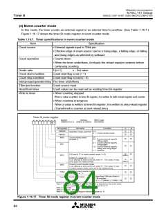
(3) Pulse period/pulse width measurement mode
In this mode, the timer measures the pulse period or pulse width of an external signal. (See Table 1.16.8.)
Figure 1.16.18 shows the timer Bi mode register in pulse period/pulse width measurement mode. Figure
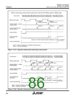
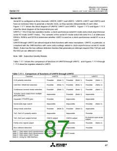
1.16.19 shows the operation timing when measuring a pulse period. Figure 1.16.20 shows the operation
timing when measuring a pulse width.
Table 1.16.8. Timer specifications in pulse period/pulse width measurement mode
Item
Count source
Count operation
Specification
f1, f8, f32, fC32
• Up count
• Counter value “000016” is transferred to reload register at measurement
pulse's effective edge and the timer continues counting
Count start flag is set (= 1)
Count start condition
Count stop condition
Count start flag is reset (= 0)
Interrupt request generation timing • When measurement pulse's effective edge is input (Note 1)
• When an overflow occurs. (Simultaneously, the timer Bi overflow flag
changes to “1”. The timer Bi overflow flag changes to “0” when the count
start flag is “1” and a value is written to the timer Bi mode register.)
TBiIN pin function
Read from timer
Measurement pulse input
When timer Bi register is read, it indicates the reload register’s content
(measurement result) (Note 2)
Write to timer
Cannot be written to
Note 1: An interrupt request is not generated when the first effective edge is input after the timer has started counting.
Note 2: The value read out from the timer Bi register is indeterminate until the second effective edge is input after the timer.
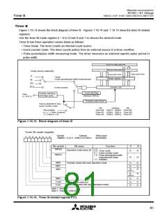
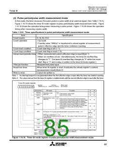
Timer Bi mode register
b7 b6 b5 b4 b3 b2 b1 b0
Symbol
Address
When reset
00XX0000
TBiMR(i=0 to 2) 039B16 to 039D16
2
1
0
R
W
Bit symbol
Bit name
Function
b1 b0
TMOD0
TMOD1
Operation mode
select bit
1 0 : Pulse period / pulse width
measurement mode
b3 b2
MR0
MR1
Measurement mode
select bit
0 0 : Pulse period measurement (Interval between
measurement pulse's falling edge to falling edge)
0 1 : Pulse period measurement (Interval between
measurement pulse's rising edge to rising edge)
1 0 : Pulse width measurement (Interval between
measurement pulse's falling edge to rising edge,
and between rising edge to falling edge)
1 1 : Inhibited
MR2
0 (Fixed to “0” in pulse period/pulse width measurement mode; i = 0)
(Note 2)
(Note 3)
Nothing is assigned (i = 1, 2).
In an attempt to write to this bit, write “0” . The value, if read, turns out to be
indeterminate.
Timer Bi overflow
flag ( Note 1)
0 : Timer did not overflow
1 : Timer has overflowed
MR3
b7 b6
TCK0
TCK1
Count source
select bit
0 0 : f
0 1 : f
1 0 : f32
1 1 : fC32
1
8
Note 1: The timer Bi overflow flag changes to “0” when the count start flag is “1” and a value is written to the
timer Bi mode register. This flag cannot be set to “1” by software.
Note 2: Timer B0.
Note 3: Timer B1, timer B2.
Figure 1.16.18. Timer Bi mode register in pulse period/pulse width measurement mode
85

 MITSUBISHI [ Mitsubishi Group ]