Mitsubishi microcomputers
M16C / 61 Group
Serial I/O
SINGLE-CHIP 16-BIT CMOS MICROCOMPUTER
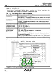
(UART0)
RxD
0
TxD
0
UART reception
Receive
clock
1/16
Reception
control circuit
Transmit/
receive
unit
Clock source selection
Clock synchronous type
Bit rate generator
f
f
f
1
Internal
(address 03A116
)
8
Transmit
clock
UART transmission
32
1/16
1 / (n0+1)
Transmission
control circuit
Clock synchronous type
External
Clock synchronous type
(when internal clock is selected)
1/2
Clock synchronous type
(when internal clock is selected)
Clock synchronous type
(when external clock is
selected)
CLK
polarity
reversing
circuit
CLK0
CTS/RTS disabled
CTS/RTS selected
RTS
0
CTS0 / RTS0
Vcc
CTS/RTS disabled
CTS/RTS separated
CTS
0
CTS0 from UART1
(UART1)
RxD1
TxD
1
UART reception
Receive
clock
1/16
Transmit/
receive
unit
Reception
control circuit
Clock source selection
Bit rate generator
(address 03A916
Clock synchronous type
f1
)
Internal
f
8
UART transmission
1/16
Transmit
clock
1 / (n1+1)
f32
Transmission
control circuit
Clock synchronous type
Clock synchronous type
(when internal clock is selected)
1/2
External
Clock synchronous type
(when internal clock is selected)
Clock synchronous type
(when external clock is
selected)
CLK
polarity
reversing
circuit
CLK1
CTS/RTS disabled
CTS/RTS separated
RTS
1
CTS
CTS
1
0
/ RTS1
V
CC
/ CLKS
1
Clock output pin
select switch
CTS/RTS disabled
CTS
1
CTS
0
CTS0 to UART0
(UART2)
TxD
RxD polarity
reversing circuit
polarity
reversing
circuit
RxD
2
TxD2
UART reception
Receive
clock
1/16
Reception
control circuit
Transmit/
receive
unit
Clock source selection
Clock synchronous type
Bit rate generator
(address 037916
f
f
f
1
Internal
)
8
UART transmission
1/16
Transmit
clock
32
1 / (n2+1)
Transmission
control circuit
Clock synchronous type
Clock synchronous type
External
(when internal clock is selected)
1/2
Clock synchronous type
(when external clock is
selected)
Clock synchronous type
(when internal clock is selected)
CLK
polarity
reversing
circuit
CLK2
CTS/RTS
selected
CTS/RTS disabled
RTS
2
CTS
2
/ RTS
2
Vcc
CTS/RTS disabled
CTS
2
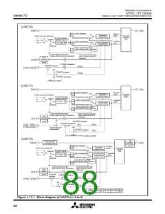
n0 : Values set to UART0 bit rate generator (BRG0)
n1 : Values set to UART1 bit rate generator (BRG1)
n2 : Values set to UART2 bit rate generator (BRG2)
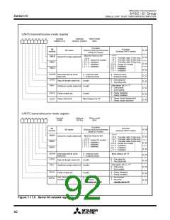
Figure 1.17.1. Block diagram of UARTi (i = 0 to 2)
88

 MITSUBISHI [ Mitsubishi Group ]