Mitsubishi microcomputers
M16C / 61 Group
SINGLE-CHIP 16-BIT CMOS MICROCOMPUTER
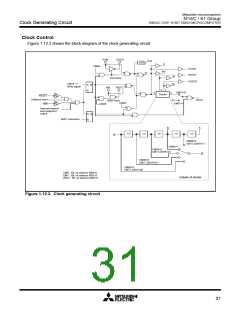
Clock Generating Circuit
Clock Generating Circuit
The clock generating circuit contains two oscillator circuits that supply the operating clock sources to the
CPU and internal peripheral units.
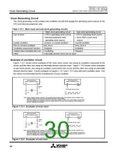
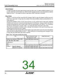
Table 1.12.1. Main clock and sub-clock generating circuits
Main clock generating circuit
• CPU’s operating clock source
• Internal peripheral units’
operating clock source
Ceramic or crystal oscillator
XIN, XOUT
Sub-clock generating circuit
• CPU’s operating clock source
• Timer A/B’s count clock
source
Use of clock
Usable oscillator
Crystal oscillator
XCIN, XCOUT
Pins to connect oscillator
Oscillation stop/restart function
Oscillator status immediately after reset
Other
Available
Available
Oscillating
Stopped
Externally derived clock can be input
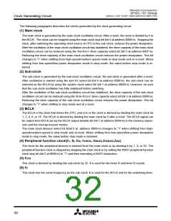
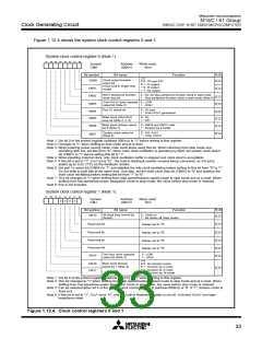
Example of oscillator circuit
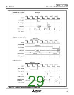
Figure 1.12.1 shows some examples of the main clock circuit, one using an oscillator connected to the
circuit, and the other one using an externally derived clock for input. Figure 1.12.2 shows some examples
of sub-clock circuits, one using an oscillator connected to the circuit, and the other one using an externally
derived clock for input. Circuit constants in Figures 1.12.1 and 1.12.2 vary with each oscillator used. Use
the values recommended by the manufacturer of your oscillator.
Microcomputer
(Built-in feedback resistor)
Microcomputer
(Built-in feedback resistor)
XIN
XOUT
XIN
XOUT
Open
(Note)
Rd
Externally derived clock
Vcc
Vss
CIN
C
OUT
Note: Insert a damping resistor if required. The resistance will vary depending on the oscillator and the oscillation drive
capacity setting. Use the value recommended by the maker of the oscillator.
When the oscillation drive capacity is set to low, check that oscillation is stable. Also, if the oscillator manufacturer's
data sheet specifies that a feedback resistor be added external to the chip, insert a feedback resistor between XIN
and XOUT following the instruction.
Figure 1.12.1. Examples of main clock
Microcomputer
(Built-in feedback resistor)
Microcomputer
(Built-in feedback resistor)
X
CIN
XCOUT
X
CIN
XCOUT
Open
(Note)
RCd
Externally derived clock
CCIN
CCOUT
Vcc
Vss
Note: Insert a damping resistor if required. The resistance will vary depending on the oscillator and the oscillation drive
capacity setting. Use the value recommended by the maker of the oscillator.
When the oscillation drive capacity is set to low, check that oscillation is stable. Also, if the oscillator manufacturer's
data sheet specifies that a feedback resistor be added external to the chip, insert a feedback resistor between XCIN
and XCOUT following the instruction.
Figure 1.12.2. Examples of sub-clock
30

 MITSUBISHI [ Mitsubishi Group ]