Mitsubishi microcomputers
M16C / 61 Group
SINGLE-CHIP 16-BIT CMOS MICROCOMPUTER
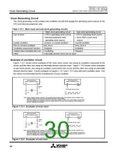
Clock Generating Circuit
Clock Control
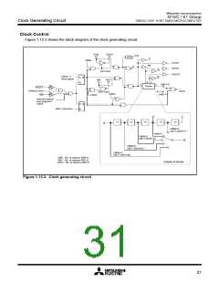
Figure 1.12.3 shows the block diagram of the clock generating circuit.
XCIN
X
COUT
fC32
1/32
f1
CM04
f1SIO2
fAD
fC
f8SIO2
f8
Sub clock
f
32SIO2
CM10 “1”
Write signal
f
32
S
R
Q
X
IN
X
OUT
b
c
CM07=0
a
d
Divider
RESET
Software reset
NMI
BCLK
f
C
Main clock
CM02
CM07=1
CM05
Interrupt request
level judgment
output
S Q
R
WAIT instruction
c
b
1/2
1/2
1/2
1/2
1/2
a
CM06=0
CM17,CM16=11
CM06=1
CM06=0
CM17,CM16=10
d
CM06=0
CM17,CM16=01
CM06=0
CM17,CM16=00
CM0i : Bit i at address 000616
CM1i : Bit i at address 000716
WDCi : Bit i at address 000F16
Details of divider
Figure 1.12.3. Clock generating circuit
31

 MITSUBISHI [ Mitsubishi Group ]