MT9300
Advance Information
cancellers that can each be configured into Back-to-
Back.
Canceller B must always be “0”. Refer to Figure 3
and to Control Register 2 for bit description.
Examples of Back-to-Back configuration include
positioning one group of echo cancellers between a
CODEC and a transmission device or between two
codecs for echo control on analog trunks.
Bypass
The Bypass state directly transfers PCM codes from
Rin to Rout and from Sin to Sout. When Bypass
state is selected, the Adaptive Filter coefficients
are reset to zero.
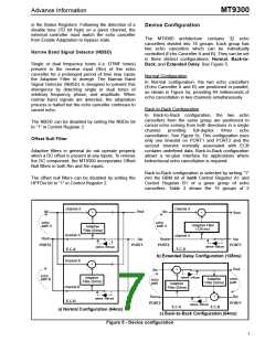
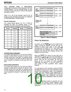
Extended Delay configuration
In this configuration, the two echo cancellers from
the same group are internally cascaded into one 128
milliseconds echo canceller. See Figure 5b. This
configuration uses only one timeslot on PORT1 and
PORT2 and the second timeslot normally associated
with ECB contains undefined data.
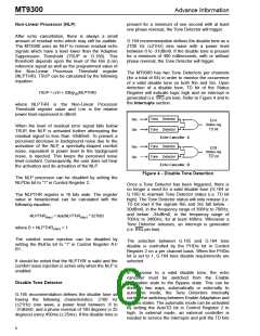
Disable Adaptation
When the Disable Adaptation state is selected, the
Adaptive Filter coefficients are frozen at their current
value. In this state, the adaptation process is halted
however the echo canceller continues to cancel
echo.
Extended Delay configuration is selected by writing
“1” into the ExtDl bit in Echo Canceller A, Control
Register A1. For a given group, only Echo Canceller
A, Control Register A1, has the ExtDl bit. Control
Register B1, bit-0 must always be set to zero.
Enable Adaptation
In Enable Adaptation state, the Adaptive Filter
coefficients are continually updated. This allows
the echo canceller to model the echo return path
characteristics in order to cancel echo. This is the
normal operating state.
Table 2 shows the 16 groups of 2 cancellers that can
each be configured into 64ms or 128ms echo tail
capacity.
The echo canceller functions are selected in Control
Register A1/B1 and Control Register 2 through four
control bits: MuteS, MuteR, Bypass and AdaptDis.
Refer to the Registers Description for details.
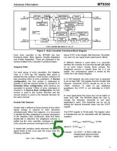
Echo Canceller Functional States
MT9300 Throughput Delay
Each echo canceller has four functional states:
Mute, Bypass, Disable Adaptation and Enable
Adaptation.
The throughput delay of the MT9300 varies
according to the device configuration. For all device
configurations, Rin to Rout has a delay of two
frames and Sin to Sout has a delay of three frames.
In Bypass state, the Rin to Rout and Sin to Sout
paths have a delay of two frames.
Mute
In Normal and in Extended Delay configurations,
writing a “1” into the MuteR bit replaces Rin with
quiet code which is applied to both the Adaptive
Filter and Rout. Writing a “1” into the MuteS bit
replaces the Sout PCM data with quiet code.
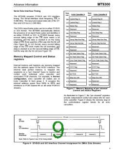
Serial PCM I/O channels
LINEAR
16 bits
SIGN/
MAGNITUDE
µ-Law
CCITT (G.711)
There are two sets of TDM I/O streams, each with
channels numbered from 0 to 31. One set of input
streams is for Receive (Rin) channels, and the other
set of input streams is for Send (Sin) channels.
Likewise, one set of output streams is for Rout pcm
channels, and the other set is for Sout channels. See
figure 6 for channel allocation.
2’s
µ-Law
FFh
A-Law
complement
A-Law
+Zero
(quiet code)
0000h
80h
D5h
Table 1 - Quiet PCM Code Assignment
In Back-to-Back configuration, writing a “1” into the
MuteR bit of Echo Canceller A, Control Register 2,
causes quiet code to be transmitted on Rout. Writing
a “1” into the MuteS bit of Echo Canceller A, Control
Register 2, causes quiet code to be transmitted on
Sout.
The arrangement and connection of PCM channels
to each echo canceller is a 2 port I/O configuration
for each set of PCM Send and Receive channels, as
illustrated in Figure 3.
In Extended Delay and in Back -to -Back
configurations, MuteR and MuteS bits of Echo
8

 MITEL [ MITEL NETWORKS CORPORATION ]