Advance Information
MT9300
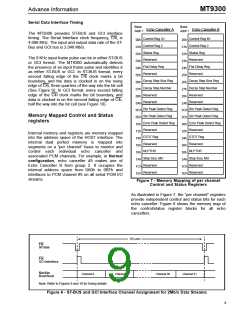
After the HOST CPU has received the channel
number of the interrupt source, the corresponding
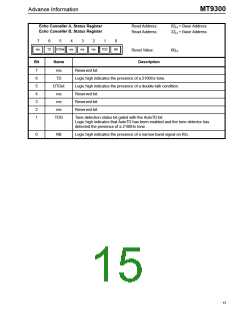
per channel Status Register can be read from
internal memory to determine the cause of the
interrupt (see Figure 7 for address mapping of Status
register). The TD bit indicates the presence of a
Tone Disable.
Power management
Each group of echo cancellers can be placed in
Power Down mode by writing a “0” into the PWUP bit
in their respective Main Control Register. When a
given group is in Power Down mode, the
corresponding PCM data are bypassed from Rin to
Rout and from Sin to Sout with two frames delay.
Refer to the Main Control Register section for
description.
The MIRQ bit 5 in the Main Control Register 0 masks
interrupts from the MT9300. To provide more
flexibility, the MTDBI (bit-4) and MTDAI (bit-3) bits in
the Main Control Register<15:0> allow Tone Disable
to be masked or unmasked, from generating an
interrupt on a per channel basis. Refer to the
Registers Description section.
The typical power consumption can be calculated
with the following equation:
PC = 60 * Nb_of_groups + 40, in mW
JTAG Support
where 0 ≤ Nb_of_groups ≤ 16
The MT9300 JTAG interface conforms to the
Boundary-Scan standard IEEE1149.1. This standard
specifies a design-for-testability technique called
Boundary-Scan test (BST). The operation of the
Boundary Scan circuitry is controlled by an external
Test Access Port (TAP) controller. JTAG inputs are
3.3 Volts compliant only.
Call Initialization
To ensure fast initial convergence on a new call, it is
important to clear the Adaptive filter. This is done by
momentarily putting the echo canceller in bypass
mode and then enabling adaptation.
Test Access Port (TAP)
Interrupts
The TAP provides access to many test functions of
the MT9300. It consists of three input pins and one
output pin. The following pins are found on the TAP.
The MT9300 provides an interrupt pin (IRQ) to
indicate to the HOST processor when a G.164 or
G.165 Tone Disable is detected and released.
•
Test Clock Input (TCK)
Although the MT9300 may be configured to react
automatically to tone disable status on any input
PCM voice channels, the user may want for the
external HOST processor to respond to Tone Disable
information in an appropriate, application specific
manner.
The TCK provides the clock for the test logic.
The TCK does not interfere with any on-chip
clock and thus remains independent. The TCK
permits shifting of test data into or out of the
Boundary-Scan register cells concurrent with
the operation of the device and without
interfering with the on-chip logic.
Each echo canceller will generate an interrupt when
a Tone Disable occurs and will generate another
interrupt when a Tone Disable releases.
•
Test Mode Select Input (TMS)
The logic signals received at the TMS input are
interpreted by the TAP Controller to control the
test operations. The TMS signals are sampled
at the rising edge of the TCK pulse. This pin is
internally pulled to VDD when it is not driven
from an external source.
Upon receiving an IRQ, the HOST CPU should read
the Interrupt FIFO Register. This register is a FIFO
memory containing the channel number of the echo
canceller that has generated the interrupt.
All pending interrupts from any of the echo
cancellers and their associated input channel
number are stored in this FIFO memory. The IRQ
always returns high after a read access to the
Interrupt FIFO Register. The IRQ pin will toggle low
for each pending interrupt.
•
Test Data Input (TDI)
Serial input data applied to this port is fed
either into the instruction register or into a test
data register, depending on the sequence
previously applied to the TMS input. Both
registers are described in a subsequent
section. The received input data is sampled at
11

 MITEL [ MITEL NETWORKS CORPORATION ]