Advance Information
MT9300
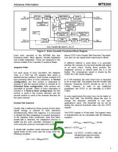
µ/A-Law/
Linear
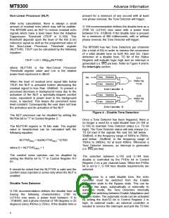
Non-Linear
Processor
Offset
Null
Linear/
µ/A-Law
Sout
(channel N)
Sin
(channel N)
+
-
Microprocessor
Disable Tone
Detector
MuteS
Interface
Double-Talk
Detector
ST-BUS
PORT2
ST-BUS
PORT1
Programmable
Bypass
Disable Tone
Detector
Narrow-Band
Detector
MuteR
Offset
Null
Linear/
µ/A-Law
12dB
Attenuator
µ/A-Law/
Linear
Rout
(channel N)
Rin
(channel N)
Echo Canceller (N), where 0 ≤ N ≤ 31
Figure 3 - Echo Canceller Functional Block Diagram
Each echo canceller in the MT9300 has four
functional states: Mute, Bypass, Disable Adaptation
and Enable Adaptation. These are explained in the
section entitled Echo Canceller Functional States.
where DTDT is the Double-Talk Detection Threshold.
Lsin and Lrin are signal levels expressed in dBm0.
A different method is used when it is uncertain
whether Sin consists of a low level double-talk signal
or an echo return. During these periods, the
adaptation process is slowed down but it is not
halted. The convergence speed is shown by the
CONV bit in the Status Register.
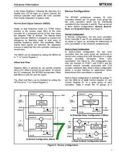
Adaptive Filter
For each group of echo cancellers, the Adaptive
Filter is a 1024 tap FIR adaptive filter which is
divided into two sections. Each section contains 512
taps providing 64ms of echo estimation. In Normal
configuration, the first section is dedicated to
channel A and the second section to channel B. In
Extended Delay configuration, both sections are
cascaded to provide 128ms of echo estimation in
channel A. In Back-to Back configuration, the first
section is used in the receive direction and the
second section is used in the transmit direction for
the same channel.
In G.168 standard, the echo return loss is expected
to be at least 6dB. This implies that the Double-Talk
Detector Threshold (DTDT) should be set to 0.5
(-6dB). However, in order to get additional
guardband, the DTDT is set internally to 0.5625
(-5dB).
In some applications the return loss can be higher or
lower than 6dB. The MT9300 allows the user to
change the detection threshold to suit each
application’s need. This threshold can be set by
writing the desired threshold value into the DTDT
register.
Double-Talk Detector
Double-Talk is defined as those periods of time when
signal energy is present in both directions
simultaneously. When this happens, it is necessary
to disable the filter adaptation to prevent divergence
of the Adaptive Filter coefficients. Note that when
double-talk is detected, the adaptation process is
halted but the echo canceller continues to cancel
echo using the previous converged echo profile.
The DTDT register is 16 bits wide. The register value
in hexadecimal can be calculated with the following
equation:
DTDT(hex) = hex(DTDT(dec) * 32768)
where 0 < DTDT(dec) < 1
A double-talk condition exists whenever the relative
signal levels of Rin (Lrin) and Sin (Lsin) meet the
following condition:
Example: For DTDT = 0.5625 (-5dB), the
hexadecimal value becomes
hex(0.5625 * 32768) = 4800h
Lsin > Lrin + 20log10(DTDT)
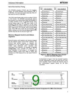
5

 MITEL [ MITEL NETWORKS CORPORATION ]