Advance Information
MT9300
in the Status Registers. Following the detection of a
disable tone (TD bit high) on a given channel, the
external controller must switch the echo canceller
from Enable Adaptation to Bypass state.
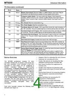
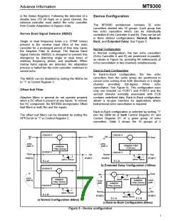
Device Configuration
The MT9300 architecture contains 32 echo
cancellers divided into 16 groups. Each group has
two echo cancellers which can be individually
controlled (Echo Canceller A and B). They can be set
in three distinct configurations: Normal, Back-to-
Back, and Extended Delay. See Figure 5.
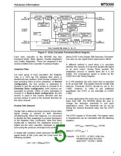
Narrow Band Signal Detector (NBSD)
Single or dual frequency tones (i.e. DTMF tones)
present in the receive input (Rin) of the echo
canceller for a prolonged period of time may cause
the Adaptive Filter to diverge. The Narrow Band
Signal Detector (NBSD) is designed to prevent this
divergence by detecting single or dual tones of
arbitrary frequency, phase, and amplitude. When
narrow band signals are detected, the adaptation
process is halted but the echo canceller continues to
cancel echo.
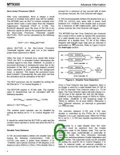
Normal Configuration
In Normal configuration, the two echo cancellers
(Echo Canceller A and B) are positioned in parallel,
as shown in Figure 5a, providing 64 milliseconds of
echo cancellation in two channels simultaneously.
Back-to-Back Configuration
In Back-to-Back configuration, the two echo
cancellers from the same group are positioned to
cancel echo coming from both directions in a single
The NBSD can be disabled by setting the NBDis bit
to “1” in Control Register 2.
channel
providing
full-duplex
64ms
echo
cancellation. See Figure 5c. This configuration uses
only one timeslot on PORT1 and PORT2 and the
second timeslot normally associated with ECB
contains undefined data. Back-to-Back configuration
allows a no-glue interface for applications where
bidirectional echo cancellation is required.
Offset Null Filter
Adaptive filters in general do not operate properly
when a DC offset is present at any inputs. To remove
the DC component, the MT9300 incorporates Offset
Null filters in both Rin and Sin inputs.
Back-to-Back configuration is selected by writing “1”
into the BBM bit of both Control Register A1 and
Control Register B1 of a given group of echo
cancellers. Table 2 shows the 16 groups of 2
The offset null filters can be disabled by setting the
HPFDis bit to “1” in Control Register 2.
channel A
channel A
Sout
Sin
Sin
+
+
Sout
-
-
echo
path A
echo
path A
Adaptive Filter
(128 ms)
Adaptive
Filter (64ms)
channel A
channel A
Rout
Rout
Rin
Rin
PORT2
PORT1
PORT2
PORT1
Optional -12dB pad
Optional -12dB pad
E.C.A
E.C.A
b) Extended Delay Configuration (128ms)
channel B
+
Sout
+
-
Sin
-
echo
path B
Optional -12dB pad
Adaptive
Filter (64ms)
Adaptive
Filter (64ms)
echo
path
echo
path
Adaptive
Filter (64ms)
channel B
-
+
Rout
Rin
PORT1
Optional -12dB pad
E.C.B
PORT2
Optional -12dB pad
E.C.A
E.C.B
a) Normal Configuration (64ms)
c) Back-to-Back Configuration (64ms)
Figure 5 - Device configuration
7

 MITEL [ MITEL NETWORKS CORPORATION ]