MT91L60
Advance Information
125 µs
F0i
DSTi,
DSTo
CHANNEL 2
B1-channel
CHANNEL 0
D-channel
CHANNEL 3
B2-channel
CHANNEL 1
C-channel
CHANNELS 4-31
Not Used
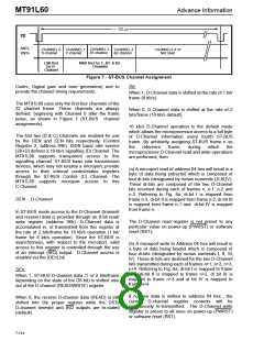
LSB first
for D-
Channel
MSB first for C, B1- & B2-
Channels
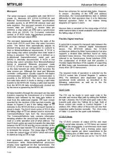
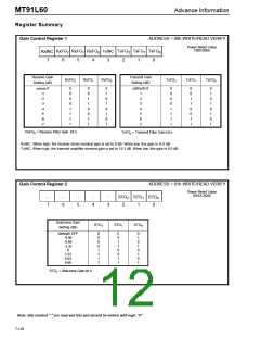
Figure 7 - ST-BUS Channel Assignment
Codec, Digital gain and tone generation) and to
provide the channel timing requirements.
D8:
When 1, D-Channel data is shifted at the rate of 1 bit/
frame (8 kb/s).
The MT91L60 uses only the first four channels of the
32 channel frame. These channels are always
defined, beginning with Channel 0 after the frame
pulse, as shown in Figure 7 (ST-BUS channel
assignments).
When 0, D-Channel data is shifted at the rate of 2
bits/frame (16 kb/s default).
16 kb/s D-Channel operation is the default mode
which allows the microprocessor access to a full byte
of D-Channel information every fourth ST-BUS
frame. By arbitrarily assigning ST-BUS frame n as
The first two (D & C) Channels are enabled for use
by the DEN and CEN bits respectively, (Control
Register 2, address 04h). ISDN basic rate service
(2B+D) defines a 16 kb/s signalling (D) Channel. The
MT91L60 supports transparent access to this
signalling channel. ST-BUS basic rate transmission
devices, which may not employ a microport, provide
access to their internal control/status registers
through the ST-BUS Control (C) Channel. The
MT91L60 supports microport access to this
C-Channel.
the
reference
frame,
during
which
the
microprocessor D-Channel read and write operations
are performed, then:
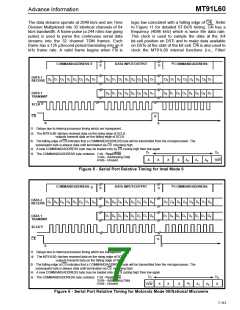
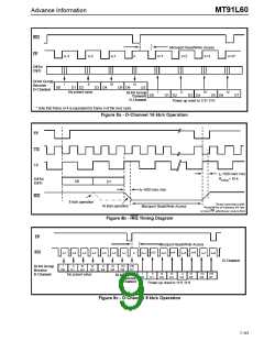
(a) A microport read of address 04 hex will result in a
byte of data being extracted which is composed of
four di-bits (designated by roman numerals I,II,III,IV).
These di-bits are composed of the two D-Channel
bits received during each of frames n, n-1, n-2 and
n-3. Referring to Fig. 8a: di-bit I is mapped from
frame n-3, di-bit II is mapped from frame n-2, di-bit III
is mapped from frame n-1 and di-bit IV is mapped
from frame n.
DEN - D-Channel
In ST-BUS mode access to the D-Channel (transmit
and receive) data is provided through an 8-bit read/
write register (address 06h). D-Channel data is
accumulated in, or transmitted from this register at
the rate of 2 bits/frame for 16 kb/s operation (1 bit/
frame for 8 kb/s operation). Since the ST-BUS is
asynchronous, with respect to the microport, valid
access to this register is controlled through the use
of an interrupt (IRQ) output. D-Channel access is
enabled via the (DEn) bit.
The D-Channel read register is not preset to any
particular value on power-up (PWRST) or software
reset (RST).
(b) A microport write to Address 04 hex will result in
a byte of data being loaded which is composed of
four di-bits (designated by roman numerals I, II, III,
IV). These di-bits are destined for the two D-Channel
bits transmitted during each of frames n+1, n+2, n+3,
n+4. Referring to Fig. 8a: di-bit I is mapped to frame
n+1, di-bit II is mapped to frame n+2, di bit III is
mapped to frame n+3 and di bit IV is mapped to
frame n+4.
DEn:
When 1, ST-BUS D-channel data (1 or 2 bits/frame
depending on the state of the D8 bit) is shifted into/
out of the D-channel (READ/WRITE) register.
If no new data is written to address 04 hex , the
current D-channel register contents will be
continuously re-transmitted. The D-Channel write
register is preset to all ones on power-up (PWRST)
or software reset (RST).
When 0, the receive D-channel data (READ) is still
shifted into the proper register while the DSTo
D-channel timeslot and IRQ outputs are tri-stated
(default).
7-114

 MITEL [ MITEL NETWORKS CORPORATION ]