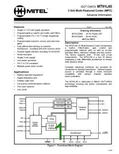
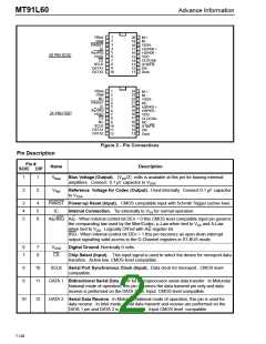
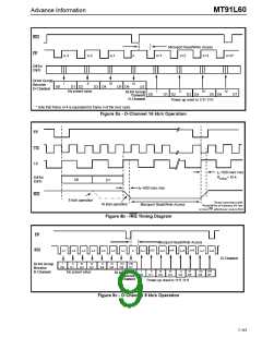
Advance Information
MT91L60
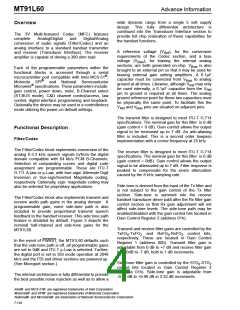
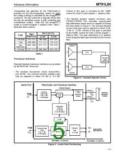
Companding law selection for the Filter/Codec is
provided by the A/µ companding control bit while
the coding scheme is controlled by the Smag/ITU-T
control bit. The A/µ control bit is logically OR’ed with
the A/µ pin providing access in both controller and
controllerless modes. Both A/µ and Smag/ITU-T
reside in Control Register 2 (address 04h). Table 1
illustrates these choices.
Control of this gain is provided by the TxINC
control bit (Gain Control register 1, address 00h).
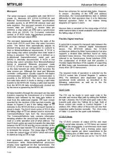
• The handset speaker outputs (receiver), pins
HSPKR+/HSPKR-.This internally compensated
fully differential output driver is capable of driving
the load shown in Figure 4. The nominal handset
receive path gain may be adjusted to either 0 dB,
-6 dB or -12 dB. Control of this gain is provided
by the RxINC control bit (Gain Control register 1,
address 00h). This gain adjustment is in addition
to the programmable gain provided by the receive
filter.
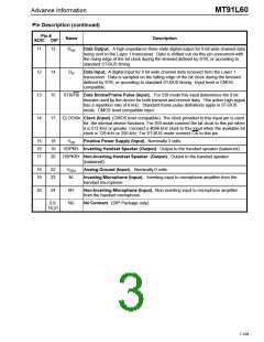
ITU-T (G.711)
Sign/
Code
Magnitude
µ-Law
A-Law
+ Full Scale
+ Zero
1111 1111
1000 0000
0000 0000
1000 0000
1111 1111
0111 1111
1010 1010
1101 0101
0101 0101
-Zero
HSPKR +
(quiet code)
- Full Scale
0111 1111
0000 0000
0010 1010
75 Ω
Table 1
150 ohm
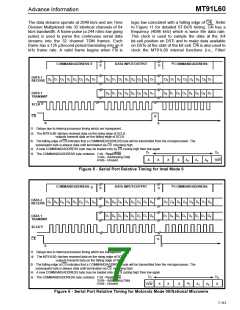
Transducer Interfaces
load
MT91L60
(speaker)
Standard handset transducer interfaces are provided
by the MT91L60. These are:
75 Ω
• The handset microphone inputs (transmitter),
pins M+/M-. The nominal transmit amplifier gain
may be adjusted to either 6.0 dB or 15.3 dB.
HSPKR -
Figure 4 - Handset Speaker Driver
Filter/Codec and Transducer Interface
Serial Port
Default Bypass
HSPKR +
-6.0 dB or
0 dB
Receiver
Driver
Receive
Filter Gain
0 to -7 dB
(1 dB steps)
Handset
Receiver
(150Ω)
PCM
75Ω
HSPKR -
-6 dB
D
in
75Ω
Side-tone
-9.96 to
+9. 96 dB
(3.32 dB steps)
-11 dB
PCM
M+
M-
Transmit
Transmit Filter
Transmit Filter
Transmitter
Microphone
Transmit Gain
Gain
Gain
Gain
-0.37 dB or 8.93 dB
0 to +7 dB
0 to +7 dB
(1 dB steps)
D
6.37 dB
out
(1 dB steps)
INTERNAL TO DEVICE
EXTERNAL TO DEVICE
Figure 3 - Audio Gain Partitioning
7-111

 MITEL [ MITEL NETWORKS CORPORATION ]