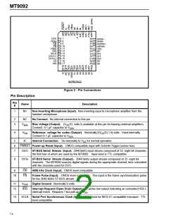
MT9092
DSTi
DSTo
C4i
F0i
VSSD
IRQ
7
8
9
39
38
37
36
35
34
33
32
31
30
29
SPKR+
SPKR-
HSPKR+
HSPKR-
VDD
BP
S12
S11
S10
S9
10
11
12
13
14
15
16
17
SCLK
DATA 2
DATA 1
CS
WD
S8
44 PIN PLCC
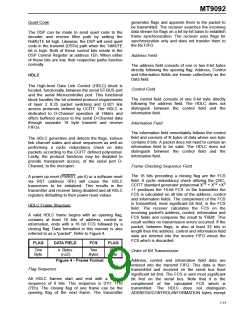
Figure 2 - Pin Connections
Pin Description
Pin
Name
#
Description
1
M+
Non-Inverting Microphone (Input). Non-inverting input to microphone amplifier from the
handset microphone.
2
3
NC
No Connect. No internal connection to this pin.
V
Bias Voltage (Output). (V /2) volts is available at this pin for biasing external amplifiers.
DD
Bias
Connect 0.1 µF capacitor to V
.
SSA
4
V
Reference voltage for codec (Output). Nominally [(V /2)-1.5] volts. Used internally.
DD
Ref
Connect 0.1 µF capacitor to V
.
SSA
5
6
7
IC
Internal Connection. Tie externally to V for normal operation.
SS
PWRST Power-up Reset (Input). CMOS compatible input with Schmitt Trigger (active low).
DSTi
ST-BUS Serial Stream (Input). 2048 kbit/s input stream composed of 32 eight bit channels;
the first four of which are used by the MT9092. Input level is TTL compatible.
8
DSTo ST-BUS Serial Stream (Output). 2048 kbit/s output stream composed of 32 eight bit
channels. The MT9092 sources digital signals during the appropriate channel, time coincident
with the channels used for DSTi.
9
C4i
F0i
4096 kHz Clock (Input). CMOS level compatible.
10
Frame Pulse (Input). CMOS level compatible. This input is the frame synchronization pulse
for the 2048 kbit/s ST-BUS stream.
11
12
V
Digital Ground . Nominally 0 volts.
SSD
IRQ
Interrupt Request (Open Drain Output). An active low output indicating an unmasked HDLC
interrupt event. Requires 1 kΩ pull-up to V
.
DD
13
SCLK Serial Port Synchronous Clock (Input). Data clock for MCS-51 compatible microport. TTL
level compatible.
7-4

 MITEL [ MITEL NETWORKS CORPORATION ]