MT9092
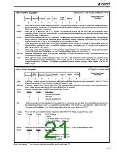
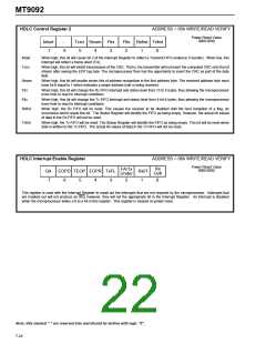
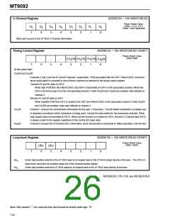
HDLC Control Register 2
ADDRESS = 05h WRITE/READ VERIFY
Power Reset Value
0000 0000
Intsel
7
-
Tcrci Seven Flrx
Fltx
2
Rxfrst Txfrst
6
5
4
3
1
0
Intsel
Tcrci
When high, this bit will cause bit 2 of the Interrupt Register to reflect a Transmit FIFO underrun (Txunder). When low, this
interrupt will reflect a frame abort (FA).
When high, this bit will inhibit transmission of the CRC. That is, the transmitter will not insert the computed CRC onto the bit
stream after seeing the EOP tag byte. The microprocessor then has the opportunity to insert the CRC as part of the data
field.
Seven
Flrx
When high, this bit will enable seven bits of address recognition in the first address byte. The received address byte must
have bit 0 equal to 1 which indicates a single address byte is being received.
When high, this bit will change the Rx FIFO interrupt and status level from 15 to 5 bytes, thus allowing the microprocessor
more time to react to interrupt conditions.
Fltx
When high, this bit will change the Tx FIFO interrupt and status level from 4 to14 bytes, thus allowing the microprocessor
more time to react to interrupt conditions.
Rxfrst
When high, the Rx FIFO will be reset. This causes the receiver to be disabled until the next reception of a flag, an
occurrence which resets this bit. The Status Register will identify the FIFO as being empty. However, the actual bit values
of data in the Rx FIFO will not be reset.
Txfrst
When high, the Tx FIFO will be reset. The Status Register will identify the FIFO as being empty. This bit will be reset when
data is written to the Tx FIFO. The actual bit values of data in the Tx FIFO will not be reset..
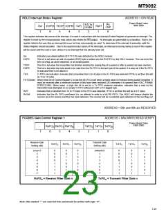
HDLC Interrupt Enable Register
ADDRESS = 06h WRITE/READ VERIFY
Power Reset Value
Rx
Ovfl
FA/Tx
Under
0000 0000
GA
7
EOPD TEOP EOPR TxFL
RxFf
1
6
5
4
3
2
0
This register is used with the Interrupt Register to mask out the interrupts that are not required by the microprocessor. Interrupts that
are masked out will not produce an IRQ; however, they will set the appropriate bit in the Interrupt Register. An interrupt is disabled
when the microprocessor writes a 0 to a bit in this register. This register is cleared on power reset.
Note: Bits marked "-" are reserved bits and should be written with logic "0".
7-24

 MITEL [ MITEL NETWORKS CORPORATION ]