MT9092
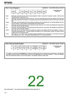
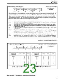
HDLC Interrupt Status Register
ADDRESS = 07h READ
Power Reset Value
0000 0000
Rx
FA/Tx
Under
GA
7
EOPD TEOP EOPR TxFL
RxFf
1
Ovfl
6
5
4
3
2
0
This register indicates the source of an interrupt. It is used in conjunction with the Interrupt Enable Register to generate an interrupt. The
register is reset by the microprocessor read, which also resets the IRQ output. All interrupts are generated by a transition. That is, the
register informs the user that an interrupt did occur but may not presently be valid. To determine if the interrupt is presently valid the
Status Register should be polled. Due to the asynchronous nature of the interrupts, an interrupt occurring during a read of this register
will be saved until the read is over, unless it is an interrupt that has already been set.
GA
Indicates a go-ahead pattern (011111110) was detected by the HDLC receiver.
EOPD
This bit is set when an end of a packet (EOP) byte is written into the RX FIFO by the HDLC receiver. This can be in the
form of a flag, an abort sequence, or an invalid packet.
TEOP
EOPR
This bit is set when the transmitter has finished sending the closing flag of a packet or after a packet has been aborted .
This bit is set when the byte about to be read from the Rx FIFO is the last byte of the packet. It is also set if the Rx FIFO
is read and there is no data in it.
TxFL
Tx FIFO low indication. Indicates that a transition from 5 to 4 bytes in the Tx FIFO was detected. If Fltx is set then this will
be 15 to 14 bytes.
FA:TxUnder When Intsel bit of Control Register 2 is low this bit (FA) is set when a frame abort is received during packet reception. It
must be received after a minimum number of bits have been received (26) otherwise it is ignored (see HDLC FRAME
STRUCTURE). When Intsel is high this bit is set for a Tx FIFO underrun indication. Indicates that a read by the
transmitter was attempted on an empty Tx FIFO without an EOP or FA tagged byte.
RxFf
Indicates that a transition from 14 to 15 bytes in the FIFO was detected. If Flrx is set then this will be 4 to 5 bytes.
RxOvfl
Indicates that the Rx FIFO overflowed (i.e. an attempt to write to a full RX FIFO). The HDLC will always disable the
receiver once the receive overflow has been detected. The receiver will be re-enabled upon detection of the next flag, but
ADDRESS = 08h and 09h are RESERVED
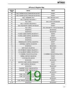
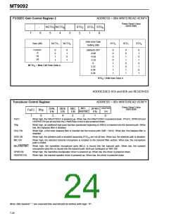
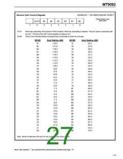
FCODEC Gain Control Register 1
ADDRESS = 0Ah WRITE/READ VERIFY
Power Reset Value
X000 X000
-
RxFG RxFG RxFG
TxFG TxFG TxFG
2 1 0
-
2
1
0
7
6
5
4
3
2
1
0
Receive Gain
Setting (dB)
Transmit Gain
Setting (dB)
RxFG2
RxFG1
RxFG0
TxFG2
TxFG1
TxFG0
(default) 0
0
0
0
0
1
1
1
1
0
0
1
1
0
0
1
1
0
1
0
1
0
1
0
1
(default) 0
0
0
0
0
1
1
1
1
0
0
1
1
0
0
1
1
0
1
0
1
0
1
0
1
-1
-2
-3
-4
-5
-6
-7
1
2
3
4
5
6
7
RxFG = Receive Filter Gain n
TxFG = Transmit Filter Gain n
n
n
Note: Bits marked "-" are reserved bits and should be written with logic "0".
7-25

 MITEL [ MITEL NETWORKS CORPORATION ]