MT9092
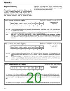
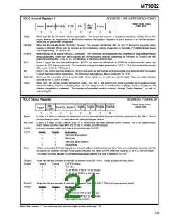
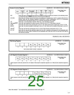
HDLC Control Register 1
Adrec HRxEN HTxEN EOP
ADDRESS = 03h WRITE/READ VERIFY
Power Reset Value
Mark
Idle
0000 0000
FA
3
Trans
1
-
7
6
5
4
2
0
Adrec
HRxEN
HTxEN
EOP
When high this bit will enable address recognition. This forces the receiver to recognize only those packets having the
unique address as programmed in the Receive Address Recognition Registers or if the address is an All-Call address.
When low, all packets are recognized.
When low this bit will disable the HDLC receiver. The receiver will disable after the rest of the packet presently being
received is finished. When high the receiver will be immediately enabled (depending on the state of CHoEN) and will begin
searching for flags, Go-aheads etc.
When low this bit will disable the HDLC transmitter. The transmitter will disable after the completion of the packet presently
being transmitted. When high the transmitter will be immediately enabled (depending on the state of CHoEN) and will
begin transmitting data, if any, or go to a Mark idle or Interframe time fill state.
Forms a tag on the next byte written to the Tx FIFO and when set will indicate an EOP byte to the transmitter which will
transmit an FCS following this byte. This facilitates loading of multiple packets into Tx FIFO. This bit is reset automatically
after a write to the Tx FIFO occurs.
FA
Forms a tag on the next byte written to Tx FIFO and when set will indicate to the transmitter that it should abort the packet
in which that byte is being transmitted. This bit is reset automatically after a write to the Tx FIFO.
Mark Idle
Trans
When low, the transmitter will be in an idle state. When high it is in an Interframe time fill state. These two states will only
occur when the Tx FIFO is empty.
When high this bit will enable transparent mode. The HDLC will perform the serial-to-parallel and parallel-to-serial
conversion without inserting or deleting zeros. No CRC bytes are sent or monitored nor are flags, aborts or Go-aheads. No
address recognition is monitored. The receiver or transmitter must be enabled through Control Register 1 as well as
setting CH0EN.
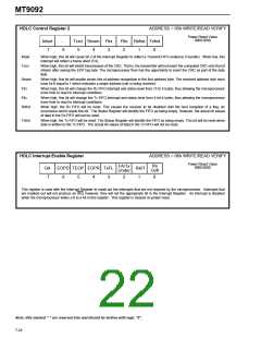
HDLC Status Register
ADDRESS = 04h READ
Power Reset Value
00XX 1000
Idle
Intgen
Txstat Txstat Rxstat Rxstat
RxBS2 RxBS1
Chan
2
1
2
1
7
6
5
4
3
2
1
0
Intgen
Is set to a 1 when an interrupt (in conjunction with the Interrupt Mask Register) has been generated by the HDLC. This is
an asynchronous event. It is reset when the Interrupt Register is read.
Idle Chan Is set to a 1 when an Idle Channel state (15 or more ones) has been detected by the receiver. This is an asynchronous
event. Status becomes valid after first 15 bits or the first zero bit received.
RxBS2,
RxBS1
Indicates the status of the next byte to be read from the Rx FIFO.
RxBS2
RxBS1
Byte status
1
0
1
0
1
1
0
0
last byte (bad packet)
first byte
last byte (good packet)
packet byte
Note
- If two consecutive first byte signals are received without an intervening last byte, then an overflow has occurred and the
first packet (or packets) are bad. A bad packet indicates that either a frame abort has occurred or the FCS did not match.
- On power-up these bits are in an indeterminate state until the first byte is written to Rx FIFO.
Txstat2,
Txstat1
These two bits are encoded to indicate the present state of Tx FIFO. This is an asynchronous event.
Txstat2
Txstat1
Tx FIFO Status
0
0
1
1
0
1
1
0
TxFULL
5 OR MORE BYTES (15 if Fltx set)
4 OR LESS BYTES (14 if Fltx set)
TxEMPTY
Rxstat2,
Rxstat1
These two bits are encoded to indicate the present state of Rx FIFO. This is an asynchronous event.
Rxstat2
Rxstat1
Rx FIFO Status
0
0
1
1
0
1
1
0
RxEMPTY
14 OR LESS BYTES (4 if Flrx set)
15 OR MORE BYTES (5 if Flrx set)
RxOVERFLOW EXISTS
Note: Bits marked "-" are reserved bits and should be written with logic "0".
7-23

 MITEL [ MITEL NETWORKS CORPORATION ]