MT9092
New Call Tone
Watchdog
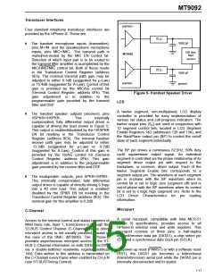
The New Call Tone Generator produces a frequency
shifted square-wave used to toggle the speaker
driver outputs. This is intended for use where a
ringing signal is required concurrently with an
already established voice conversation in the
handset.
To maintain program integrity an on-chip watchdog
timer is provided for connection to the
microcontroller reset pin. The watchdog output WD
(pin 17) goes high while the HPhone-II is held in
reset via the PWRST (pin 6). Release of PWRST will
cause WD to return low immediately and will also
start the watchdog timer. The watchdog timer is
clocked on the falling edge of F0i and requires only
Programming of the DSP for New Call generator is
exactly as is done for the tone ringer micro-program
except that the OPT bit (DSP Control Register,
address 1Eh) is set high. In this mode the DSP does
not produce a frequency shifted squarewave output
to the filter CODEC section. Instead the DSP uses
the contents of the tone coefficient registers, along
with the tone warble rate register, to produce a gated
squarewave control signal output which toggles
between the programmed frequencies. This control
signal is routed to the New Call Tone block when the
NCT EN control bit is set (General Control Register,
address 0Fh). NCT EN also enables a separate gain
control block, for controlling the loudness of the
generated ringing signal. With the gain control block
set to 0dB the output is at maximum or 6 volts p-p.
Attenuation of the applied signal, in three steps of 8
dB, provide the four settings for New Call tone (0, -8,
this input, along with V , for operation.
DD
If the watchdog reset word is written to the watchdog
register (address 11h) after PWRST is released, but
before the timeout period (T=512mSec) expires, a
reset of the timer results and WD will remain low.
Thereafter, if the reset word is loaded correctly at
intervals less than 'T' then WD will continue low. The
first break from this routine, in which the watchdog
register is not written to within the correct interval or
it is written to with incorrect data, will result in a high
going WD output after the current interval 'T' expires.
WD will then toggle at this rate until the watchdog
register is again written to correctly.
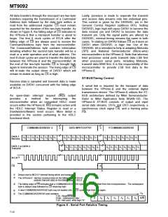
5-BIT WATCHDOG RESET WORD
-16, -24 dB). The NCT gain bits (NCTG -NCTG )
reside in the FCODEC Gain Control Register 2
0
1
W4 W3 W2
W1
W0
(address 0Bh).
X
X
X
0
1
0
1
0
x=don’t care
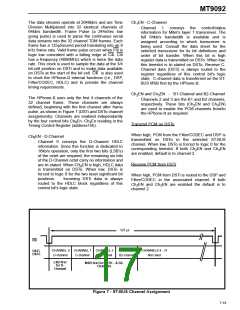
Test Loops
Detail LBio and LBoi Loopback Register (address
16h)
LBio Setting this bit causes data on DSTi to be
looped back to DSTo directly at the pins. The
appropriate channel enables Ch EN -Ch EN
0
3
must also be set.
LBoi Setting this bit causes data on DSTo to be
looped back to DSTi directly at the pins.
7-20

 MITEL [ MITEL NETWORKS CORPORATION ]