MT90826 CMOS
Advanced Information
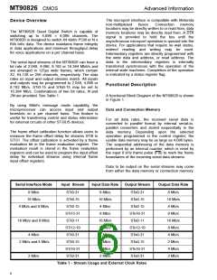
16Mb/s mode (DR2=0, DR1=0, DR0 =1)
The internal master clock, which has a fixed
relationship with the CLK and F0i depending upon
the mode of operation, is used as the reference
timing signal to determine the input frame delays.
See Figure 4 for the signal alignments between the
internal and the external master clocks.
When the 16Mb/s mode is selected, the device is
configured with 16-input/16-output data streams
each having 256 64Kbit/s channels. This mode
allows a maximum non-blocking capacity of 4,096 x
4,096 channels.
A measurement cycle is started by setting the start
frame evaluation (SFE) bit low for at least one frame.
Then the evaluation starts when the SFE bit in the
control register is changed from low to high. Two
frames later, the complete frame evaluation (CFE) bit
of the frame alignment register changes from low to
high to signal that a valid offset measurement is
ready to be read from bits 0 to 9 of the FAR register.
The SFE bit must be set to zero before a new
measurement cycle started.
4Mb/s and 8Mb/s mode (DR2=0, DR1=1, DR0=0)
When the 4Mb/s and 8Mb/s mode is selected, the
device is configured with 32-input/32-output data
streams. STi0-15/STo0-15 have a data rate of 4Mb/s
and STi16-31/STo16-31 have a data rate of 8Mb/s.
This mode allows a maximum non-blocking capacity
of 3,072 x 3,072 channels.
16Mb/s and 8Mb/s mode (DR2=0, DR1=1, DR0=1)
When the 16Mb/s and 8Mb/s mode is selected, the
device is configured with 20-input/20-output data
streams. STi0-11/STo0-11 have a data rate of 16Mb/
s and STi12-19/STo12-19 have a data rate of 8Mb/s.
This mode allows a maximum non-blocking capacity
of 4,096 x 4,096 channels.
The falling edge of the frame measurement signal
(FEi) is evaluated against the falling edge of the
frame pulse (F0i). See Table 7 for the description of
the frame alignment register.
Input Frame Offset Selection
4Mb/s mode (DR2=1, DR1=0, DR0=0)
When the 4Mb/s mode is selected, the device is
configured with 32-input/32-output data streams
each having 64 64Kbit/s channels. This mode allows
a maximum non-blocking capacity of 2,048 x 2,048
channels.
Input frame offset selection allows the channel
alignment of individual input streams, which operate
at 4.096Mb/s, 8.192Mb/s or 16.384Mb/s, to be
shifted against the input frame pulse (F0i). The input
offset selection is not available for streams operated
at 2.048Mb/s. This feature is useful in compensating
for variable path delays caused by serial backplanes
of variable lengths, which may be implemented in
large centralized and distributed switching systems.
2Mb/s and 4Mb/s mode (DR2=1, DR1=0, DR0=1)
When the 2Mb/s and 4Mb/s mode is selected, the
device is configured with 32-input/32-output data
streams. STi0-15/STo0-15 have a data rate of 2Mb/s
and STi16-31/STo16-31 have a data rate of 4Mb/s.
This mode allows a maximum non-blocking capacity
of 1,536 x 1,536 channels.
Each input stream has its own delay offset value
programmed by the input delay offset registers. Each
delay offset register can control 4 input streams.
There are eight delay offset registers (DOS0 to
DOS7) to control 32 input streams. Possible
adjustment can range up to +4.5 internal master
clock periods forward with resolution of 1/2 internal
master clock period. See Table 8 and Table 9 for
frame input delay offset programming.
2Mb/s mode (DR2=1, DR1=1, DR0 =0)
When the 2Mb/s mode is selected, the device is
configured with 32-input/32-output data streams
each having 32 64Kbit/s channels. This mode allows
a maximum non-blocking capacity of 1,024 x 1,024
channels.
Output Advance Offset Selection
Serial Input Frame Alignment Evaluation
The MT90826 allows users to advance individual
output streams up to 45ns with a resolution of 15ns
when the device is in 8Mb/s, 16Mb/s, 4 and 8 Mb/s or
16 and 8 Mb/s mode. The output delay adjustment is
useful in compensating for variable output delays
caused by various output loading conditions. The
frame output offset registers (FOR0 & FOR3) control
the output offset delays for each output streams via
the programming of the OFn bits.
The MT90826 provides the frame evaluation inputs,
FEi0 to FEi31, to determine different data input
delays with respect to the frame pulse F0i. By using
the frame evaluation input select bits (FE0 to FE4) of
the frame alignment register (FAR), users can select
one of the thirty-two frame evaluation inputs for the
frame alignment measurement.
8

 MITEL [ MITEL NETWORKS CORPORATION ]