MT90826 CMOS
Advanced Information
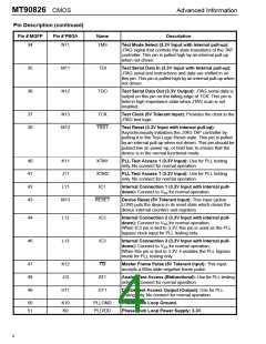
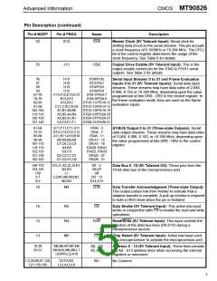
Pin Description (continued)
Pin # MQFP
Pin # PBGA
Name
Description
34
N11
TMS
Test Mode Select (3.3V Input with Internal pull-up):
JTAG signal that controls the state transitions of the TAP
controller. This pin is pulled high by an internal pull-up
when not driven.
35
36
M11
N12
TDI
Test Serial Data In (3.3V Input with Internal pull-up):
JTAG serial test instructions and data are shifted in on
this pin. This pin is pulled high by an internal pull-up when
not driven.
TDO
Test Serial Data Out (3.3V Output): JTAG serial data is
output on this pin on the falling edge of TCK. This pin is
held in high impedance state when JTAG scan is not
enabled.
37
38
N13
M12
TCK
Test Clock (5V Tolerant Input): Provides the clock to the
JTAG test logic.
TRST
Test Reset (3.3V Input with internal pull-up):
Asynchronously initializes the JTAG TAP controller by
putting it in the Test-Logic-Reset state. This pin is pulled
by an internal pull-up when not driven. This pin should be
pulsed low on power-up, or held low, to ensure that the
device is in the normal functional mode.
40
41
42
43
K11
J11
L11
M13
XTM1
XTM2
IC1
PLL Test Access 1 (3.3V Input): Use for PLL testing
only. No connect for normal operation.
PLL Test Access 1 (3.3V Input): Use for PLL testing
only. No connect for normal operation.
Internal Connection 1 (3.3V Input with internal pull-
down): Connect to VSS for normal operation.
RESET
Device Reset (5V Tolerant Input): This input (active
LOW) puts the device in its reset state which clears the
device internal counters and registers.
44
46
L12
L13
IC2
IC3
Internal Connection 2 (3.3V Input with internal pull-
down): Connect to VSS for normal operation.
When IC3 pin is tied to 3.3V, this pin is used as the PLL
bypass clock input for PLL testing only.
Internal Connection 3 (3.3V Input with internal pull-
down): Connect to VSS for normal operation.
When this pin is tied to 3.3V, it enables the PLL bypass
mode for PLL testing only.
47
48
49
K12
J12
H11
F0i
AT1
DT1
Master Frame Pulse (5V Tolerant Input): This input
accepts a 60ns wide negative frame pulse.
Analog Test Access (Bidirectional): Use for PLL testing
only. No connect for normal operation.
Digital Test Access Output (Output): Use for PLL
testing only. No connect for normal operation.
50
51
K10
K9
PLLGND
PLLVDD
Phase Lock Loop Ground.
Phase Lock Loop Power Supply: 3.3V
4

 MITEL [ MITEL NETWORKS CORPORATION ]