MT9079
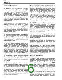
ST-BUS bit 7 is synonymous with PCM 30 bit 1; bit 6
with bit 2: and so on. See Figure 33.
functions such as bit error rate estimation. The
CRC-4 multiframe consists of 16 basic frames
numbered 0 to 15, and has a repetition rate of 16
frames X 125 microseconds/frame = 2 msec. CRC-4
multiframe alignment is based on the 001011 bit
sequence, which appears in bit position one of the
first six NFASs of a CRC-4 multiframe.
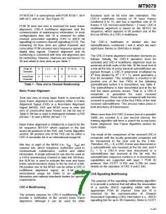
PCM 30 time slot zero is reserved for basic frame
alignment, CRC-4 multiframe alignment and the
communication of maintenance information. In most
configurations time slot 16 is reserved for either
channel associated signalling (CAS or ABCD bit
signalling) or common channel signalling (CCS). The
remaining 30 time slots are called channels and
carry either PCM encoded voice frequency signals or
digital data signals. Channel alignment and bit
numbering is consistent with time slot alignment and
bit numbering. However, channels are numbered 1 to
30 and relate to time slots as per Table 1.
The CRC-4 multiframe is divided into two
submultiframes, numbered 1 and 2, which are each
eight basic frames or 2048 bits in length.
The CRC-4 frame alignment verification functions as
follows. Initially, the CRC-4 operation must be
activated and CRC-4 multiframe alignment must be
achieved at both ends of the link. At the local end of
a link all the bits of every transmit submultiframe are
passed through a CRC-4 polynomial (multiplied by
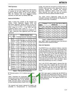
PCM 30
Timeslots
0
1 2 3 ....15
1 2 3 ....15
16
X
17 18 19 ....31
16 17 18 ....30
4
4
X then divided by X + X + 1), which generates a
four bit remainder. This remainder is inserted in bit
position one of the four FASs of the following
submultiframe before it is transmitted, see Table 4.
The submultiframe is then transmitted and at the far
end the same process occurs. That is, a CRC-4
remainder is generated for each received
submultiframe. These bits are compared with the bits
received in position one of the four FASs of the next
received submultiframe. This process takes place in
both directions of transmission.
Voice/Data
Channels
X
Table 1 - Time slot to Channel Relationship
Basic Frame Alignment
Time slot zero of every basic frame is reserved for
basic frame alignment and contains either a Frame
Alignment Signal (FAS) or a Non-frame Alignment
Signal (NFAS). FAS and NFAS occur in time slot
zero of consecutive basic frames as can be see in
Table 4. Bit two is used to distinguish between a FAS
(bit two = 0) and a NFAS (bit two = 1).
When more than 914 CRC-4 errors (out of a possible
1000) are counted in a one second interval, the
framing algorithm will force a search for a new basic
frame alignment. See Frame Algorithm section for
more details.
Basic frame alignment is initiated by a search for the
bit sequence 0011011 which appears in the last
seven bit positions of the FAS, see Frame Algorithm
section. Bit position one of the FAS can be either a
CRC-4 remainder bit or an international usage bit.
The result of the comparison of the received CRC-4
remainder with the locally generated remainder will
be transported to the near end by the E-bits.
Therefore, if E = 0, a CRC-4 error was discovered in
a submultiframe one received at the far end; and if
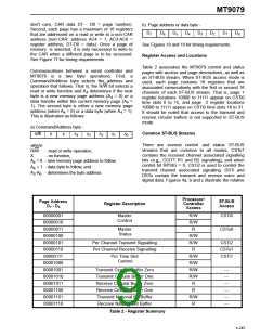
Bits four to eight of the NFAS (i.e., S - S ) are
1
a4
a8
national bits, which telephone authorities used to
communicate maintenance, control and status
information. A single national bit can also be used as
a 4 KHz maintenance channel or data link. Bit three,
the ALM bit, is used to indicate the near end basic
frame synchronization status to the far end of a link.
Bit position one of the NFAS can be either a CRC-4
multiframe alignment signal, an E-bit or an
international usage bit. Refer to an approvals
laboratory and national standards bodies for specific
requirements.
E
= 0, a CRC-4 error was discovered in a
2
submultiframe two received at the far end. No
submultiframe sequence numbers or re-transmission
capabilities are supported with layer 1 PCM 30
protocol. See CCITT G.704 and G.706 for more
details on the operation of CRC-4 and E-bits.
CAS Signalling Multiframing
The purpose of the signalling multiframing algorithm
is to provide a scheme that will allow the association
of a specific ABCD signalling nibble with the
appropriate PCM 30 channel. Time slot 16 is
reserved for the communication of Channel
Associated Signalling (CAS) information (i.e., ABCD
signalling bits for up to 30 channels). Refer to CCITT
CRC-4 Multiframing
The primary purpose for CRC-4 multiframing is to
provide a verification of the current basic frame
alignment, although it can be used for other
4-243

 MITEL [ MITEL NETWORKS CORPORATION ]