MT9079
A
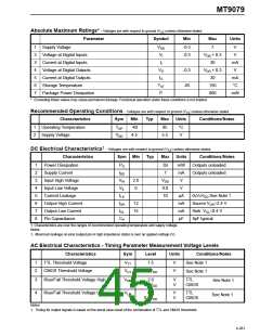
START
TAIS input = low
is Interface
TE?
YES
TE bit = 1
Power-on Reset - RESET
input = RC > = 5 x power
supply rise time
NO
Mask and unmask
interrupts. Note 1.
SPND bit = 1
Select ST-BUS offset.
Note 1.
Write 00H to all control
registers of pages 7 & 8
Select PCM 30 line
encoding. Note 1.
Select mode of operation.
Note 1.
Clear the error counters
of page 4. Note 2.
Select National bit, data
link, and AIS mode of
operation. Note 1.
Read interrupt vector
register, page 4. Note 3.
8KSEL bit = 1 if using the
E8Ko output for loop
(slave) timing. Note 1.
SPND = 0.
Note 3.
Notes:
1. Skip if default option is required.
A
2. Skip if counters are not used.
3. Skip if interrupts are not used.
TAIS input = high
STOP
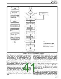
Figure 12 - MT9079 Initialization Procedure
The TE control bit sets the state of the transmit
E-bits when the receive side has lost CRC-4
synchronization. In this case if the interface is the
Terminal Equipment (TE) side, then the E-bits must
be zero. If the interface is the Network Termination
(NT) side, the transmit E-bits must be one when
Adjusting the ST-BUS offset will move the bit
positions of the ST-BUS output streams with respect
to the input frame pulse F0i. This can be used to
compensate for large delays in very long backplane
applications. It can also be used to minimize the
delay through the receive elastic buffer.
CRC-4 synchronization is lost.
When CRC-4
synchronization is achieved the transmit E-bits will
function according to ITU-T G.704.
Selection of the PCM 30 encoding will be determined
by the line interface arrangement used. The default
is HDB3 encoding on bipolar non-return to zero
signals, which will interface directly to most Line
Interface Units (LIU).
The MT9079 has a suite of 30 maskable interrupts.
At this point in the initialization procedure the SYNI,
RAII, AISI, AIS16I, LOSI, FERI, BPVO and SLPI
interrupts will be unmasked and all others will be
masked. If the application does not require
interrupts, the SPND control bit should be kept at
one.
After a power-on reset the state of the error counters
of page 4 will be undetermined. Therefore, each of
the counters appropriate to the application should be
cleared by writing a zero value to the counter
4-277

 MITEL [ MITEL NETWORKS CORPORATION ]