MT9079
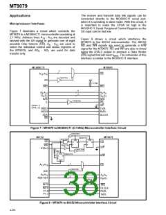
The receive and transmit data link signals can be
connected directly to the MC68HC11 serial port,
when it is operating is slave mode. With this circuit, it
is important to make the CPHA bit high in the
MC68HC11 Serial Peripheral Control Register so the
SS input can be tied low.
Applications
Microprocessor Interfaces
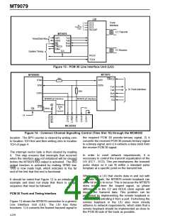
Figure 7 illustrates a circuit which connects the
MT9079 to a MC68HC11 microcontroller operating at
2.1 MHz. Address lines A - A are decoded and
13
15
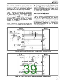
Figure 8 shows a circuit which interfaces the
MT9079 to the 80C52 microcontroller. The 80C52
RD and WR signals are used to generate a R/W
signal for the MT9079. RD and WR are also re-timed
using the XTAL2 output to produce a Data Strobe
latched with the AS signal to generate one of eight
possible Chip Selects (CS). A - A are used to
8
12
select the individual control and status registers of
the MT9079, and AD - AD are used for data
0
7
transfer only.
(DS) signal that will meet t
. The remainder of this
RWS
interface is similar to the MC68HC11 interface.
MC68HC11
MT9079
3
A
-A
CS
13 15
74HCT04
+5V
AS
4.7kΩ
IRQ
IRQ
5
8
A -A
A -A
0 4
8
12
D -D
D -D
0
7
0
7
R/W
E
R/W
DS
74HCT04
S/P
TxDL
RxDL
DLCLK
(CPHA = 1)
(CPOL = 0)
MISO
MOSI
SCK
SS
Figure 7 - MT9079 to MC68HC11 (2.1 MHz) Microcontroller Interface Circuit
74HCT04
80C52
MT9079
74HCT74
74HCT08
74HCT04
PR
PR
RD
D
Q
D
Q
DS
WR
S/P
XTAL2
74HCT04
+5V
10kΩ
PR
74HCT74
R/W
D
Q
CLR
3
A
-A
CS
13 15
74HCT04
ALE
5
A -A
A -A
8
12
0
4
8
AD0-AD7
D -D
0
7
+5V
10kΩ
INT0
IRQ
INT1
P1.0
P1.1
DLCLK
RxDL
TxDL
Figure 8 - MT9079 to 80C52 Microcontroller Interface Circuit
4-274

 MITEL [ MITEL NETWORKS CORPORATION ]