MT9079
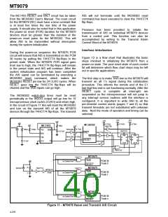
The MC1455 RESET and HALT circuit has be taken
from the MC68302 User's Manual. The reset circuit
for the MT9079 (RC) must have a time constant that
is at least five times the rise time of the power
supply. It should also be noted that in this application
the power-on reset (POR) duration for the MT9079
devices must be greater than the duration of the
power-on reset pulse for the MC68302. This will
allow AIS to be transmitted without interruption
during the system initialization.
AIS will not terminate until the MC68302 reset
command has been executed to clear the 74HCT74
flip-flops.
Provision has been provided to initiate the
transmission of AIS on individual MT9079 devices
from a control port. This function can also be
accomplished by writing to the Transmit Alarm
Control Word of the MT9079.
Interface Initialization
During the power-on sequence the MT9079 POR
circuit will ensure that AIS is transmitted on the PCM
30 trunks by putting the 74HCT74 flip-flops in the
preset state. When the MT9079 POR signal goes
from low to high, the 74HCT74 flip-flops will remain
in the preset state and AIS will continue. After the
system initialization program has been completed
the AIS signal can be terminated by executing a
MC68302 reset command, which makes the
MC68302 RESET pin low for 24 CLKO cycles. When
RESET goes low the 74HCT74 flip-flops will be
cleared and the TAIS inputs can go high.
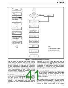
Figure 12 is a flow chart that illustrates the basic
steps involved in initializing the MT9079 from a
power-on state. The post reset state of each control
bit will determine which flow chart steps may be left
out in specific applications.
The first step is to make TAIS low so the MT9079 will
transmit an all 1’s signal during the initialization
procedure. This informs the remote end of the E1
link that this end is not functioning normally. After the
RESET cycle is complete all interrupts are
suspended so the microprocessor will not jump to
any interrupt service routines until the interface is
configured. It is important to write 00H to all the
per-timeslot control words (pages 7 and 8) so that
transmit timeslots are not substituted with unknown
data. Next the mode of operation and timing can be
selected.
The MC68302 watch-dog timer must be reset
periodically or the WDOG output will go low for 16
microprocessor clock cycles (CLKO) and return high.
In the circuit of Figure 11 this will reset the MC68302
and turn on the transmit AIS of all the MT9079
devices through the 74HCT74 flip-flops. The transmit
+5V
+5V
+5V
4.7kΩ
+5V
+5V
4.7kΩ
4.7kΩ
MC68302
+5V
1MΩ
MC1455
+5V
74HCT05
IN4148
4.7kΩ
+5V
1MΩ
10kΩ
74HCT05
74HCT05
TH
RS
TR
CV
DIS
O
74HCT74
PR
0.47µF
HALT
74HCT05
74HCT05
74HCT05
PR
WDOG
12kΩ
D
Q
D
Q
RESET
Q
CLR
Q
0.1µF
CLR
74HCT32
MT9079
TAIS
RESET
MT9079
74HCT11
74HCT11
+5V
PCM 30
Trunk 0
to Control Port
to Control Port
R
C
IN4148
74HCT14
V
MT9079
POR
R
TAIS
PCM 30
Trunk 1
RESET
.
.
.
.
.
.
.
.
MT9079
74HCT11
TAIS
RESET
PCM 30
Trunk n
to Control Port
Figure 11 - MT9079 Reset and Transmit AIS Circuit
4-276

 MITEL [ MITEL NETWORKS CORPORATION ]