MT9079
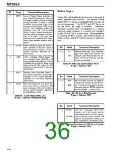
Status Page 4
Bit
Name
Functional Description
4
LOSS
Loss of Signal Status Indication. If
one, indicates the presence of a loss
of signal condition. If zero, indicates
normal operation. A loss of signal
condition occurs when there is an
absence of the receive PCM 30 sig-
nal for 255 contiguous pulse (bit)
positions from the last received
pulse. A loss of signal condition ter-
minates when an average ones den-
sity of at least 12.5% has been
received over a period of 255 contig-
uous pulse positions starting with a
pulse.
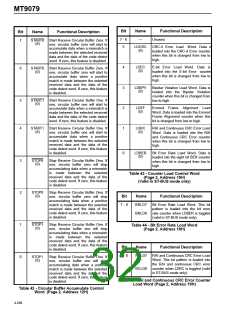
Tables 59 to 66 describe the bit functions of the page 4
status registers and counters. The Internal Vector
Status Word is cleared automatically after it is read by
the microprocessor. The RESET and RST functions
do not affect the page 4 counters.
Therefore,
individual counters must be initialized to a starting
value by a write operation or a counter load operation
(Table 43) in ST-BUS control mode. When presetting
or clearing the BPV counter, BPV7-BPV0 should be
written to first, and BPV15-BPV8 should be written to
last.
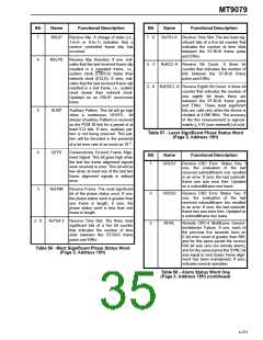
3
2
AIS16S
AISS
Alarm Indication Signal 16 Status. If
one, indicates an all ones alarm is
being received in channel 16. If zero,
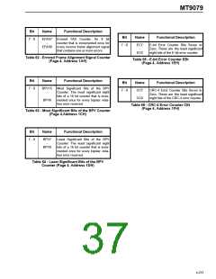
Bit
Name
Functional Description
7 - 0
IV7
-
IV0
Interrupt Vector Bits 7 to 0. The inter-
rupt vector status word contains an
interrupt vector that indicates the cat-
egory of the last interrupt. See the
section on interrupts.
normal operation. Updated on
frame basis.
a
Alarm Indication Status Signal. If
one, indicates that a valid AIS or all
ones signal is being received. If zero,
indicates that a valid AIS signal is not
being received. The criteria for AIS
detection is determined by the con-
trol bit ASEL.
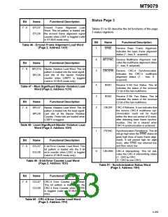
Table 59 - Interrupt Vector Status Word
(Page 4, Address 12H)
1
0
RAIS
Remote Alarm Indication Status. If
one, there is currently a remote alarm
condition. If zero, normal operation.
Updated on a non-frame alignment
frame basis.
Bit
Name
Functional Description
7 - 0
BR7
-
BR0
Bit Error Rate Counter. An eight bit
counter that contains the total num-
ber of bit errors received in a specific
time slot. See the BFAS control bit
function of page 1, address 1AH.
RCRS
RAI and Continuous CRC Error Sta-
tus. If one, there is currently an RAI
and continuous CRC error condition.
If zero, normal operation. Updated on
a submultiframe basis.
Table 60 - Bit Error Rate Counter
(Page 4, Address 18H)
Table 58 - Alarm Status Word One
(Page 3, Address 19H) (continued)
Bit
Name
Functional Description
7 - 0
RCRC7 RAI and Continuous CRC Error
-
Counter. An 8 bit counter that is
incremented once for every concur-
RCRC0 rent occurrence of the receive RAI
equal to one and either E-bit equal to
zero. Updated on a multiframe basis.
Table 61 - RAI and Continuous CRC Error Counter
(Page 4, Address 19H)
4-272

 MITEL [ MITEL NETWORKS CORPORATION ]