MT9079
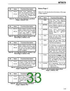
Status Page 3
Bit
Name
Functional Description
7 - 0
EFLD7
-
EFLD0
Errored Frame Alignment Load
Word. This bit pattern is loaded into
the errored frame alignment signal
counter when LDEF is toggled (valid
in ST-BUS mode only).
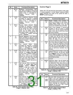
Tables 51 to 58 describe the bit functions of the page
3 status registers.
Bit
Name
Functional Description
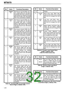
Table 46 - Errored Frame Alignment Load Word
(Page 2, Address 1AH)
7
SYNC
Receive Basic Frame Alignment.
Indicates the basic frame alignment
status (1 - loss; 0 - acquired).
6
5
MFSYNC Receive Multiframe Alignment. Indi-
cates the multiframe alignment status
(1 - loss; 0 -acquired).
Bit
Name
Functional Description
7 - 0
BPLD15 Bipolar Violation Load Word. This bit
CRCSYN Receive CRC-4 Synchronization.
Indicates the CRC-4 multiframe
-
pattern is loaded into the most signifi-
cant bits of the bipolar Violation
counter when LDBPV is toggled
(valid in ST-BUS mode only).
BPLD8
alignment status (1
acquired).
- loss; 0 -
4
3
2
REB1
REB2
Receive E-Bit One Status. This bit
indicates the status of the received
E1 bit of the last multiframe.
Table 47 - Most Significant Bipolar Violation Load
Word (Page 2, Address 1CH)
Receive E-Bit Two Status. This bit
indicates the status of the received
E2 bit of the last multiframe.
Bit
Name
Functional Description
CRCRF
CRC-4 Reframe. A one indicates that
the receive CRC-4 multiframe syn-
chronization could not be found
within the time out period of 8 msec.
after detecting basic frame synchro-
nization. This bit is cleared when
CRC-4 synchronization is achieved.
7 - 0
BPLD7
-
BPLD0
Bipolar Violation Load Word. This bit
pattern is loaded into the least signifi-
cant bits of the Bipolar Violation
Counter. These bits are loaded when
LDBPV is toggled.
Table 48 - Least Significant Bipolar Violation Load
Word (Page 2, Address 1DH)
1
0
PSYNC
Synchronization Persistence. This bit
will go high when the SYNC status bit
goes high (loss of basic frame align-
ment). It will persist high for eight
msec. after SYNC has returned low,
and then return low.
Bit
Name
Functional Description
7 - 0
ECLD7
-
ECLD0
E-bit Error Counter Load Word. This
bit pattern is loaded into the E-bit
error counter when LDEC is toggled
(valid in ST-BUS mode only).
CRCIWK CRC-4 Interworking. This bit indi-
cates the CRC-4 interworking status
(1 - CRC-to-CRC;
0 - CRC-to-non-CRC).
Table 49 - E-bit Error Counter Load Word
(Page 2, Address 1EH)
Table 51 - Synchronization Status Word
(Page 3, Address 10H)
Bit
Name
Functional Description
7 - 0
CCLD7
-
CCLD0
CRC-4 Error Counter Load Word.
This bit pattern is loaded into the
CRC-4 Error Counter when LDCRC
is toggled (valid in ST-BUS mode
only).
Table 50 - CRC-4 Error Counter Load Word
(Page 2, Address 1FH)
4-269

 MITEL [ MITEL NETWORKS CORPORATION ]