MT9079
Bit
Name
Functional Description
Unused.
Bit
Name
Functional Description
7 - 6
5
---
7
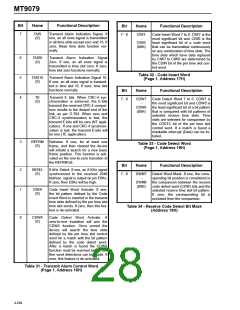
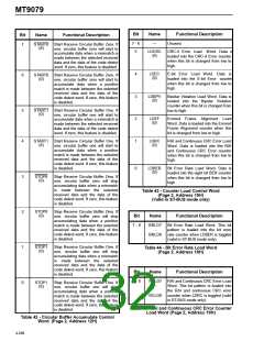
START0 Start Receive Circular Buffer Zero. If
(0)
one, circular buffer zero will start to
accumulate data when a mismatch is
made between the selected received
data and the data of the code detect
word. If zero, this feature is disabled.
LDCRC
(0)
CRC-4 Error Load Word. Data is
loaded into the CRC-4 Error counter
when this bit is changed from low to
high.
4
3
2
1
LDEC
(0)
E-bit Error Load Word. Data is
loaded into the E-bit Error counter
when this bit is changed from low to
high.
6
START0 Start Receive Circular Buffer Zero. If
(0)
one, circular buffer zero will start to
accumulate data when a positive
match is made between the selected
received data and the data of the
code detect word. If zero, this feature
is disabled.
LDBPV
(0)
Bipolar Violation Load Word. Data is
loaded into the Bipolar Violation
counter when this bit is changed from
low to high.
5
4
START1 Start Receive Circular Buffer One. If
(0)
one, circular buffer one will start to
accumulate data when a mismatch is
made between the selected received
data and the data of the code detect
word. If zero, this feature is disabled.
LDEF
(0)
Errored Frame Alignment Load
Word. Data is loaded into the Errored
Frame Alignment counter when this
bit is changed from low to high.
START1 Start Receive Circular Buffer One. If
LDRC
(0)
RAI and Continuous CRC Error Load
Word. Data is loaded into the RAI
and Continuous CRC Error counter
when this bit is changed from low to
high.
(0)
one, circular buffer one will start to
accumulate data when a positive
match is made between the selected
received data and the data of the
code detect word. If zero, this feature
is disabled.
0
LDBER
(0)
Bit Error Rate Load Word. Data is
loaded into the eight bit BER counter
when this bit is changed from low to
high.
3
2
1
0
STOP0
(0)
Stop Receive Circular Buffer Zero. If
one, circular buffer zero will stop
accumulating data when a mismatch
is made between the selected
received data and the data of the
code detect word. If zero, this feature
is disabled.
Table 43 - Counter Load Control Word
(Page 2, Address 15H)
(Valid in ST-BUS mode only)
STOP0
(0)
Stop Receive Circular Buffer Zero. If
one, circular buffer zero will stop
accumulating data when a positive
match is made between the selected
received data and the data of the
code detect word. If zero, this feature
is disabled.
Bit
Name
Functional Description
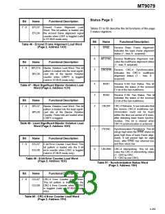
7 - 0
BRLD7
-
BRLD0
Bit Error Rate Load Word. This bit
pattern is loaded into the bit error
rate counter when LDBER is toggled
(valid in ST-BUS mode only).
STOP1
(0)
Stop Receive Circular Buffer One. If
one, circular buffer one will stop
accumulating data when a mismatch
is made between the selected
received data and the data of the
code detect word. If zero, this feature
is disabled.
Table 44 - Bit Error Rate Load Word
(Page 2, Address 18H)
Bit
Name
Functional Description
7 - 0
RCLD7
-
RAI and Continuous CRC Error Load
Word. This bit pattern is loaded into
the RAI and continuous CRC error
counter when LDRC is toggled (valid
in ST-BUS mode only).
STOP1
(0)
Stop Receive Circular Buffer One. If
one, circular buffer one will stop
accumulating data when a positive
match is made between the selected
received data and the data of the
code detect word. If zero, this feature
is disabled.
RCLD0
Table 45 - RAI and Continuous CRC Error Counter
Load Word (Page 2, Address 19H)
Table 42 - Circular Buffer Accumulate Control
Word (Page 2, Address 12H)
4-268

 MITEL [ MITEL NETWORKS CORPORATION ]