MT9079
Bit
Name
Functional Description
Bit
Name
Functional Description
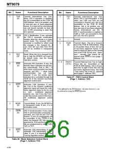
7
RDLY
(0)
Receive Delay. If one, the receive
elastic buffer will be one frame in
length and controlled frame slips will
not occur. The RSLIP and RSLPD
status bit will indicate a buffer under-
flow or overflow. If zero, the two
frame receive elastic buffer and con-
trolled slip functions are activated.
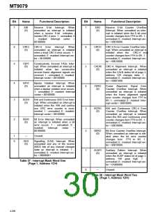
7
SYNI
(0)
Synchronization Interrupt. When
unmasked an interrupt is initiated
when a loss of basic frame synchro-
nization condition exists. If
0 -
unmasked, 1 - masked. Interrupt vec-
tor = 10000000.
6
5
4
3
2
RAII
(0)
Remote Alarm Indication Interrupt.
When unmasked a received RAI will
initiate an interrupt. If 0 - unmasked,
6
5
SPND
(0)
Suspend Interrupts. If one, the IRQ
output will be in a high-impedance
state and all interrupts will be
ignored. If zero, the IRQ output will
function normally.
1
-
masked.
Interrupt vector
=
01000000.
AISI
(0)
Alarm Indication Signal Interrupt.
When unmasked a received AIS will
initiate an interrupt. If 0 - unmasked,
INTA
(0)
Interrupt
Acknowledge.
A
zero-to-one or one-to-zero transition
will clear any pending interrupt and
make IRQ high. All interrupts must be
cleared with this bit when ST-BUS
access mode is used.
1
-
masked.
Interrupt vector
=
01000000.
AIS16I
(0)
Channel 16 Alarm Indication Signal
Interrupt. When unmasked
a
received AIS16 will initiate an inter-
rupt. If 0 - unmasked, 1 - masked.
Interrupt vector = 01000000.
4
3
TxCAS
(0)
Transmit Channel Associated Signal-
ling. If zero, the transmit section of
the device is in CAS mode. If one, it
is in common channel signalling
mode.
LOSI
(0)
Loss of Signal Interrupt. When
unmasked an interrupt is initiated
when
a loss of signal condition
RPSIG
(0)
Register Programmed Signalling. If
one, the transmit CAS signalling will
be controlled by programming page
5. If zero, the transmit CAS signalling
will be controlled through the CSTi2
stream. This bit has no function in
ST-BUS mode.
exists. If 0 - unmasked, 1 - masked.
Interrupt vector = 01000000.
FERI
(0)
Frame
Error
Interrupt.
When
unmasked an interrupt is initiated
when an error in the frame alignment
signal occurs. If 0 - unmasked, 1 -
masked.
Interrupt
vector
=
=
2
BFAS
(0)
Bit Error Count on Frame Alignment
Signal. If zero, individual errors in bits
2 to 8 of the receive FAS will incre-
ment the Bit Error Rate Counter
(BERC). If one, bit errors in the com-
parison between receive circular
buffer one and the bit error rate com-
pare word will be counted.
00100000.
1
0
BPVO
(0)
Bipolar Violation Counter Overflow
Interrupt. When unmasked an inter-
rupt is initiated when the bipolar vio-
lation error counter changes form
FFFFH to 0H. If 0 - unmasked, 1 -
masked.
00010000.
Interrupt
vector
1 - 0
---
Unused.
SLPI
(0)
SLIP Interrupt. When unmasked an
interrupt is initiated when a controlled
frame slip occurs. If 0 - unmasked, 1
Table 35 - Interrupt, Signalling and BERT Control
Word
(Page 1, Address 1AH)
-
masked. Interrupt vector
=
00000100.
Table 36 - Interrupt Mask Word Zero
(Page 1, Address 1BH
4-265

 MITEL [ MITEL NETWORKS CORPORATION ]