MT9079
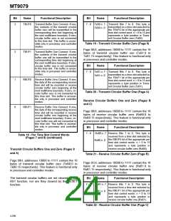
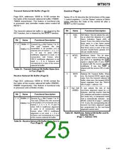
Transmit National Bit Buffer (Page D)
Control Page 1
Page 0DH, addresses 10000 to 10100 contain the
five bytes of the transmit national bit buffer (TNBB0 -
TNBB4 respectively). This feature is functional only
in processor and controller modes when control bit
NBTB=1.
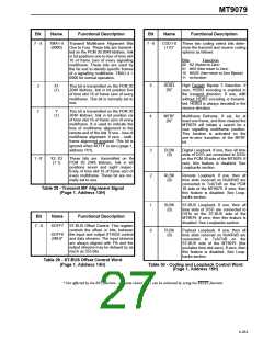
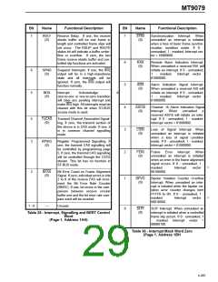
Tables 25 to 39 describe the bit functions of the page
1 control registers. ( ) in the “Name” column of these
tables indicates the state of the control bit after a
RESET or RST function.
Bit
Name
Functional Description
The transmit national bit buffer is not cleared by the
RST function, but is cleared by the RESET function.
7
ASEL
(0)
AIS Select. This bit selects the crite-
ria on which the detection of a valid
Alarm Indication Signal (AIS) is
based. If zero, the criteria is less than
three zeros in a two frame period
(512 bits). If one, the criteria is less
than three zeros in each of two con-
secutive double-frame periods (512
bits per double-frame).
Bit
Name
Functional Description
Bits Frames 1 to 15.
7 - 0 TNBBn .F1 Transmit S
an+4
-
This byte contains the bits
transmitted in bit position n+4 of
channel zero of frames 1, 3, 5, 7, 9,
11, 13 and 15 when CRC-4
multiframe alignment is used, or of
consecutive odd frames when
CRC-4 multiframe alignment is not
used. n = 0 to 4 inclusive and
corresponds to a byte of the receive
national bit buffer.
TNBBn.F15
6
MFSEL
(0)
Multiframe Select. This bit deter-
mines which receive multiframe sig-
nal (CRC-4 or signalling) the RxMF
signal is aligned with. If zero, RxMF
is aligned with the receive signalling
multiframe. If one, the RxMF is
aligned with the receive CRC-4 multi-
frame.
Table 23 - Transmit National Bit Buffer Bytes Zero
to Four (Page D)
5
NBTB
(0)
National Bit Transmit Buffer. When
one, the transmit NFAS signal origi-
nates from the transmit national bit
buffer; when zero, the transmit NFAS
signal originates from the TNU4-8
bits of page 1, address 12H.
Receive National Bit Buffer (Page E)
Page 0EH, addresses 10000 to 10100 contain the
five bytes of the receive national bit buffer (RNBB0 -
RNBB4 respectively). This feature is functional only
in processor and controller modes.
4 - 0
Sa4 - Sa8
(00000)
A
one selects the bits of the
non-frame alignment signal for a 4
kbits/sec. data link channel. Data link
(DL) selection will function in termina-
tion mode only; in transparent mode
Sa4 is automatically selected - see
MODE control bit of page 1, address
11H. If zero, the corresponding bits of
transmit non-frame alignment signal
are programmed by the non-frame
alignment control word.
Bit
Name
Functional Description
Bits Frames 1 to 15.
7 - 0 RNBBn .F1 Receive S
an+4
-
This byte contains the bits received
in bit position n+4 of channel zero of
frames 1, 3, 5, 7, 9, 11, 13 and 15
when CRC-4 multiframe alignment
is used, or of consecutive odd
frames when CRC-4 multiframe
alignment is not used. n = 0 to 4
inclusive and corresponds to a byte
of the receive national bit buffer.
RNBBn.F15
Table 25 - Multiframe, National Bit Buffer and DL
Selection Word
(Page 1, Address 10H)
Table 24 - Receive National Bit Buffer Bytes Zero to
Four (Page E)
4-261

 MITEL [ MITEL NETWORKS CORPORATION ]