MT9079
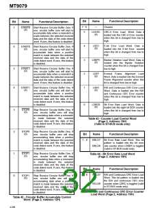
Bit
Name
Functional Description
Bit
Name
Functional Description
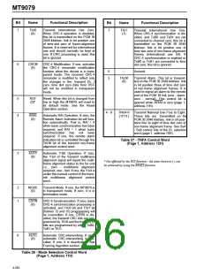
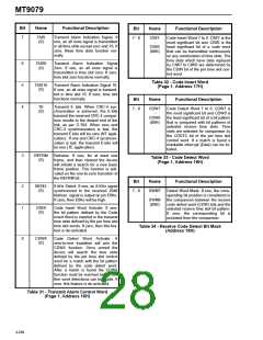
7
TAIS
(0)
Transmit Alarm Indication Signal. If
one, an all ones signal is transmitted
in all time slots except zero and 16. If
zero, these time slots function nor-
mally.
7 - 0
CIW7
-
CIW0
(00H)
Code Insert Word 7 to 0. CIW7 is the
most significant bit and CIW0 is the
least significant bit of a code word
that can be transmitted continuously
on any combination of time slots. The
time slots which have data replaced
by CIW7 to CIW0 are determined by
the CDIN bit of the per time slot con-
trol word.
6
5
4
TAIS0
(0)
Transmit Alarm Indication Signal
Zero. If one, an all ones signal is
transmitted in time slot zero. If zero,
time slot zero functions normally.
Table 32 - Code Insert Word
(Page 1, Address 17H)
TAIS16
(0)
Transmit Alarm Indication Signal 16.
If one, an all ones signal is transmit-
ted in time slot 16. If zero, time slot
functions normally.
Bit
Name
Functional Description
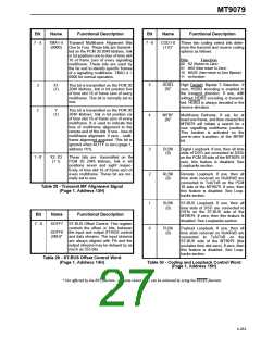
TE
(0)
Transmit E bits. When CRC-4 syn-
chronization is achieved, the E-bits
transmit the received CRC-4 compar-
ison results to the distant end of the
link, as per G.704. When zero and
CRC-4 synchronization is lost, the
transmit E-bits will be zero (NT appli-
cation). If one and CRC-4 synchroni-
zation is lost, the transmit E-bits will
be one (TE application).
7 - 0
CDW7
-
CDW0
(00H)
Code Detect Word 7 to 0. CDW7 is
the most significant bit and CDW0 is
the least significant bit of a bit pattern
that is compared with bit patterns of
selected receive time slots. Time
slots are selected for comparison by
the CDDTC bit of the per time slot
control word. If a match is found a
maskable interrupt (Data) can be ini-
tiated.
3
REFRM
(0)
Reframe. If one, for at least one
frame, and then cleared the device
will initiate a search for a new basic
frame position. This function is acti-
vated on the one-to-zero transition of
the REFRM bit.
Table 33 - Code Detect Word
(Page 1, Address 18H)
Bit
Name
Functional Description
2
1
8KSEL
(0)
8 kHz Select. If one, an 8 KHz signal
synchronized to the received 2048
kbit/sec. signal is output on pin E8Ko.
If zero, then E8Ko will be high.
7 - 0
DWM7
-
DWM0
(00H)
Detect Word Mask. If one, the corre-
sponding bit position is considered in
the comparison between the receive
code detect word (CDW) bits and the
selected receive time slot bit pattern.
If zero, the corresponding bit is
excluded from the comparison.
CIWA
(0)
Code Insert Word Activate. If one,
the bit pattern defined by the Code
Insert Word is inserted in the transmit
time slots defined by the per time slot
time slot words. If zero, then this fea-
ture is de-activated.
Table 34 - Receive Code Detect Bit Mask
(Address 19H)
0
CDWA
(0)
Code Detect Word Activate.
A
zero-to-one transition will arm the
CDWA function. Once armed the
device will search the time slots
defined by the per time slot control
word for a match with the bit pattern
defined by the code detect word.
After a match is found the CDWA
function must be rearmed before fur-
ther word detections can be made. If
zero, this feature is de-activated.
Table 31 - Transmit Alarm Control Word
(Page 1, Address 16H)
4-264

 MITEL [ MITEL NETWORKS CORPORATION ]