MT9079
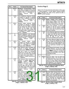
Control Page 2
Bit
Name
Functional Description
7
MFSYI
(0)
Multiframe Synchronization Inter-
rupt. When unmasked an interrupt is
initiated when multiframe synchroni-
zation is lost. 1 - unmasked, 0 -
Tables 40 to 50 describe the bit functions of the page
2 control registers. ( ) in the “Name” column of these
tables indicates the state of the control bit after a
RESET or RST function.
masked.
10000000.
Interrupt
vector
=
6
5
CSYNI
(0)
CRC-4 Multiframe Alignment. When
unmasked an interrupt is initiated
when CRC-4 multiframe synchroni-
zation is lost. 1 - unmasked, 0 -
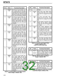
Bit
Name
Functional Description
7
BPVE Bipolar Violation Error Insertion.
(0) zero-to-one transition of this inserts a
A
masked.
Interrupt
vector
=
10000000.
single bipolar violation error into the
transmit PCM 30 data. A one, zero or
one-to-zero transition has no function.
RFALI
(0)
Remote Failure Interrupt. When
unmasked an interrupt is initiated
when the near end detects a failure
of the remote end CRC-4 process
based on the receive E-bit error
count. See the RFAIL status bit
description of page 3, address 19H. 1
- unmasked, 0 - masked. Interrupt
vector = 10000000.
6
5
CRCE CRC-4 Error Insertion. A zero-to-one
(0)
transition of this bit inserts a single
CRC-4 error into the transmit PCM 30
data. A one, zero or one-to-zero transi-
tion has no function.
FASE Frame Alignment Signal Error Insertion.
(0)
A zero-to-one transition of this bit inserts
a single error into the time slot zero
frame alignment signal of the transmit
4
YI
(0)
Remote Multiframe Loss Interrupt.
When unmasked an interrupt is initi-
ated when a remote multiframe alarm
signal is received. 1 - unmasked, 0 -
PCM 30 data.
A
one, zero or
one-to-zero transition has no function.
masked.
Interrupt
vector
=
4
3
NFSE Non-frame Alignment Signal Error Inser-
(0)
10000000.
tion. A zero-to-one transition of this bit
inserts a single error into bit two of the
time slot zero non-frame alignment sig-
nal of the transmit PCM 30 data. A one,
zero or one-to-zero transition has no
function.
3
2
1SECI
(0)
One
Second
Status. When
unmasked an interrupt is initiated
when the 1SEC status bit changes
state. 1 - unmasked, 0 - masked.
Interrupt vector = 00001000.
STOP
(0)
Stop Interrupt. When unmasked an
interrupt is initiated when either
STOP0, STOP1, STOP0 or STOP1 is
high and a match or a mismatch
between the received data, and the
data in the code detect word (CDW)
and detect word mask (DWM). 1 -
unmasked, 0 - masked. Interrupt vec-
tor = 00000010.
LOSE Loss of Signal Error Insertion. If one, the
(0)
MT9079 transmits an all zeros signal
(no pulses) in every PCM 30 time slot.
When HDB3 encoding is activated no
violations are transmitted. If zero, data is
transmitted normally.
2 - 1
0
---
Unused.
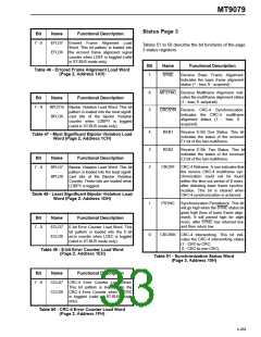
DBNCE Debounce Select. This bit selects the
(0)
debounce period (1 for 14 msec.; 0 for
no debounce). Note: there may be as
much as 2 msec. added to this duration
because the state change of the signal-
ling equipment is not synchronous with
the PCM 30 signalling multiframe.
1
STRT
(0)
Start Interrupt. When unmasked an
interrupt is initiated when either
START0, START1, START0 or
START1 is high and a match or a
mismatch is made between the
received data, and the data in the
code detect word (CDW) and detect
word mask (DWM). 1 - unmasked, 0 -
Table 40 - Error and Debounce Selection Word
(Page 2, Address 10H)
masked.
00000010.
Interrupt
vector
=
Bit
Name
Functional Description
0
DATA
(0)
Data Interrupt. When unmasked an
interrupt is initiated when the data
received in selected time slots (per
time slot control words) matches the
data in the code detect word (CDW).
1 - unmasked, 0 - masked. Interrupt
vector = 00000010.
7 - 0
CMP7 Bit Error Rate Compare Word 7 to 0.
CMP7 is the most significant bit and
-
CMP0 CMP0 is the least significant bit of a bit
(00H) pattern that is compared with the data of
the selected receive circular buffer one.
When individual bit mismatches are
detected the Bit Error Rate Counter
(BERC) is incremented.
Table 39 - Interrupt Mask Word Three
(Page 1, Address 1EH)
Table 41 - Bit Error Rate Compare Word
(Page 2, Address 11H)
4-267

 MITEL [ MITEL NETWORKS CORPORATION ]