MT9079
Bit
Name
Functional Description
Bit
Name
Functional Description
7 - 4
TMA1-4
(0000)
Transmit Multiframe Alignment Bits
One to Four. These bits are transmit-
ted on the PCM 30 2048 kbit/sec. link
in bit positions one to four of time slot
16 of frame zero of every signalling
multiframe. These bits are used by
the far end to identify specific frames
of a signalling multiframe. TMA1-4 =
0000 for normal operation.
7 - 6
COD1-0
(1 0)*
These two coding select bits deter-
mine the transmit and receive coding
options as follows:
Bits
Function
00 RZ (Return to Zero)
01 NRZ (Non-return to Zero)
10 NRZB (Non-return to Zero Bipolar)
11 no function
5
4
HDB3
(0)*
High Density Bipolar 3 Selection. If
zero, HDB3 encoding is enabled in
the transmit direction. If one, AMI
without HDB3 encoding is transmit-
ted. HDB3 is always decoded in the
receive direction.
3
2
X1
(1)
This bit is transmitted on the PCM 30
2048 kbit/sec. link in bit position five
of time slot 16 of frame zero of every
multiframe. This bit is normally set to
one.
Y
(1)
This bit is transmitted on the PCM 30
2048 kbit/sec. link in bit position six
of time slot 16 of frame zero of every
multiframe. It is used to indicate the
loss of multiframe alignment to the
remote end of the link. If one - loss of
multiframe alignment; if zero - multi-
frame alignment acquired. This bit is
ignored when AUTY is zero (page 1,
address 11H).
MFRF
(0)*
Multiframe Reframe. If set, for at
least one frame, and then cleared the
MT9079 will initiate a search for a
new signalling multiframe position.
This function is activated on the
one-to-zero transition of the MFRF
bit.
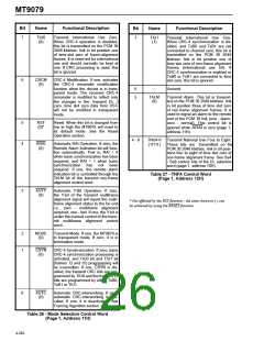
3
2
DLBK
(0)
Digital Loopback. If one, then all time
slots of DSTi are connected to DSTo
on the PCM 30 side of the MT9079. If
zero, this feature is disabled. See
Loopbacks section.
1 - 0
X2, X3
(1 1)
These bits are transmitted on the
PCM 30 2048 kbit/sec. link in bit
positions seven and eight respec-
tively, of time slot 16 of frame zero of
every multiframe. These bit are nor-
mally set to one.
RLBK
(0)
Remote Loopback. If one, then all
time slots received on RxA/RxB are
connected to TxA/TxB on the PCM
30 side of the MT9079. If zero, then
this feature is disabled. See Loop-
backs section.
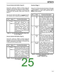
Table 28 - Transmit MF Alignment Signal
(Page 1, Address 13H)
1
0
SLBK
(0)
ST-BUS Loopback. If one, then all
time slots of DSTi are connected to
DSTo on the ST-BUS side of the
MT9079. If zero, then this feature is
disabled. See Loopbacks section.
Bit
Name
Functional Description
7 - 0
SOFF7
-
SOFF0
(00H)*
ST-BUS Offset Control. This register
controls the offset, in bits, between
the input and output ST-BUS control
and data streams. The input streams
are always aligned with F0i and the
output streams may be delayed by as
much as 255 bits.
PLBK
(0)
Payload Loopback. If one, then all
time slots received on RxA/RxB are
connected to TxA/TxB on the
ST-BUS side of the MT9079 (this
excludes time slot zero). If zero, then
this feature is disabled. See Loop-
backs section.
Table 29 - ST-BUS Offset Control Word
(Page 1, Address 14H)
Table 30 - Coding and Loopback Control Word
(Page 1, Address 15H)
* Not affected by the RST function - the state shown in ( ) can be achieved by using the RESET function.
4-263

 MITEL [ MITEL NETWORKS CORPORATION ]