MT9079
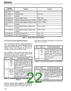
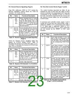
Per Channel Receive Signalling (Page 6)
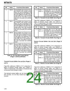
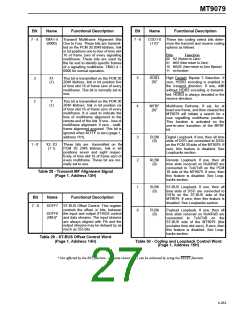
Per Time Slot Control Words (Pages 7 and 8)
Page 06H, addresses 10001 to 11111 contain the
Receive Signalling Control Words for PCM 30
channels 1 to 15 and 16 to 30.
The control functions described by Table 18 are
repeated for each ST-BUS time slot. When ST-BUS
access is selected, the programmed CSTi1 time slot
corresponds to the controlled ST-BUS or PCM 30
time slot. It should be noted that the two receive and
two transmit circular buffers are not accessible in
ST-BUS mode.
Bit
Name
Functional Description
7 - 4
A(n),
B(n),
C(n)
&
Receive Signalling Bits for Channel
n. These bits are received on the
PCM 30 2048 kbit/sec. link in bit
positions one to four of time slot 16 in
frame n (where n = 1 to 15), and are
the A, B, C, D signalling bits associ-
ated with channel n.
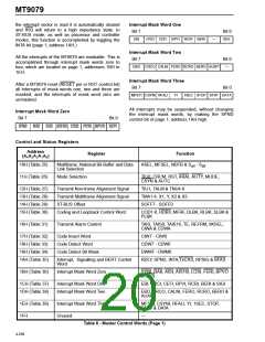
In processor and controller modes, pages 7 and 8
contain the 32 per time slot control words. Page 7
addresses 10000 to 11111 correspond to time slots 0
to 15, while page 8 addresses 10000 to 11111
correspond to time slots 16 to 31. These control bits
are not cleared by the RESET or RST reset
functions.
D(n)
3 - 0
A(n+15), Receive Signalling Bits for Channel n
B(n+15), + 15. These bits are received on the
C(n+15) PCM 30 2048 kbit/sec. link in bit
&
positions five to eight of time slot 16
D(n+15) in frame n (where n = 1 to 15), and
are the A, B, C, D signalling bits
associated with channel n + 15.
Bit
Name
Functional Description
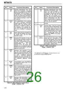
7
CDIN
Code Insert Activation. If one, the
data of CIW7-0 is transmitted in the
corresponding PCM 30 time slot. If
zero, the data on DSTi is transmitted
on the corresponding PCM 30 time
slot.
Table 15 - Receive Channel Associated Signalling
(Page 6)
Serial per channel receive signalling status bits
appear on ST-BUS stream CSTo1. Table 16
describes the function of ST-BUS time slots 1 to 15,
and Table 17 describes the function of ST-BUS time
slots 17 to 31 of CSTo1.
6
CDDTC Code Detect Activation. If one, the
data received on the corresponding
PCM 30 time slot is compared with
the unmasked bits of the code detect
word. When the DATA interrupt is
unmasked and this positive match is
made, an interrupt will be initiated. If
zero, the data is not be compared to
the unmasked bits of the code detect
word.
Bit
Name
Functional Description
7 - 4
A(n),
B(n),
C(n)
&
Receive Signalling Bits for Channel
n. These bits are received on the
PCM 30 2048 kbit/sec. link in bit
positions one to eight of time slot 16
in frame n (where n = 1 to 15), and
are the A, B, C, D signalling bits
associated with channel n.
D(n)
5
4
RTSL
Remote Time Slot Loopback. If one,
the corresponding PCM 30 receive
time slot is looped to the correspond-
ing PCM 30 transmit time slot. This
received time slot will also be present
on DSTo. An ST-BUS offset may
force a single frame delay. If zero, the
loopback is disabled.
3 - 0
---
Unused - high output level.
Table 16 - Receive CAS Channels 1 to 15 (CSTo1)
Bit
Name
Functional Description
LTSL
Local Time Slot Loopback. If one, the
corresponding transmit time slot is
looped to the corresponding receive
time slot. This transmit time slot will
also be present on the transmit PCM
30 stream. An ST-BUS offset may
force a single frame delay. If zero,
this loopback is disabled.
7 - 4
A(n+15), Receive Signalling Bits for Channel n
B(n+15), + 15. These bits are received on the
C(n+15) PCM 30 2048 kbit/sec. link in bit
&
positions five to eight of time slot 16
D(n+15) in frame n (where n = 1 to 15), and
are the A, B, C, D signalling bits
associated with channel n + 15.
3 - 0
---
Unused - high output level.
Table 18 - Per Time Slot Control Words
(Pages 7 and 8) (continued)
Table 17 - Receive CAS Channels 17 to 31 (CSTo1)
4-259

 MITEL [ MITEL NETWORKS CORPORATION ]