Preliminary Information
MT9075A
Manufacturer
For Tx
For Rx
Tx
0.68uF
1:2
2.4Ω*
2.4Ω*
Filtran
Pulse Engineering
Midcom
5721-1
PE-65351
50027
5721-2
PE-64934
50026
TTIP
TRING
OSEC
02934/A
02935/A
* 2.4 Ω resistors are only
required with 75 Ω coax
Table 1 - Transformer Manufacturers and Part
Numbers
MT9075A
1:1
Timing Source
RTIP
120Ω/
75Ω
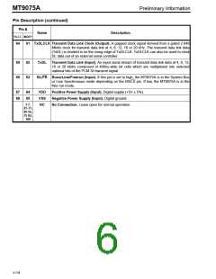
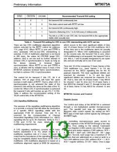
The MT9075A can use either a clock or crystal,
connecting to pins OSC1 and OSC2, as the
reference timing source.
RRING
Rx
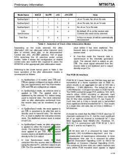
Figure 6 shows a 20MHz clock oscillator, with 50ppm
tolerance, directly connected to the OSC1 pin of the
MT9075A.
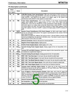
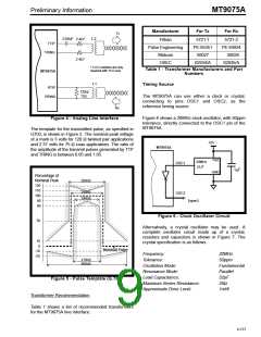
Figure 4 - Analog Line Interface
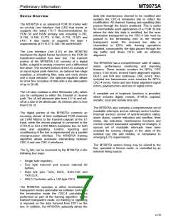
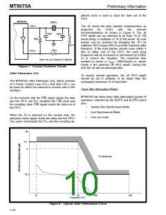
The template for the transmitted pulse, as specified in
G703, is shown in Figure 5. The nominal peak voltage
of a mark is 3 volts for 120 Ω twisted pair applications
and 2.37 volts for 75 Ω coax applications. The ratio of
the amplitude of the transmit pulses generated by TTP
and TRING is between 0.95 and 1.05.
+5V
MT9075A
Vdd
20MHz
OSC1
OUT
.1µF
GND
Percentage of
Nominal Peak
269nS
120
110
100
90
244nS
194nS
OSC2
(open)
80
Figure 6 - Clock Oscillator Circuit
50
Alternatively, a crystal oscillator may be used. A
complete oscillator circuit made up of a crystal,
resistors and capacitors is shown in Figure 7. The
crystal specification is as follows.
10
0
Nominal Pulse
-10
-20
Frequency:
20MHz
50ppm
Fundamental
Parallel
32pF
219nS
488nS
Tolerance:
Oscillation Mode:
Resonance Mode:
Load Capacitance:
Maximum Series Resistance:
Approximate Drive Level:
Figure 5 - Pulse Template (G.703)
35Ω
1mW
Transformer Recommendation
Table 1 shows a list of recommended transformers
for the MT9075A line interface.
4-137

 MITEL [ MITEL NETWORKS CORPORATION ]