MT9075A
Preliminary Information
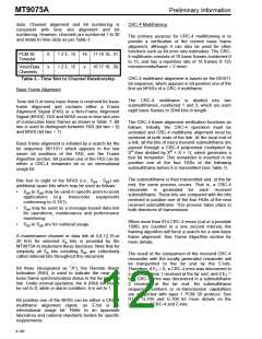
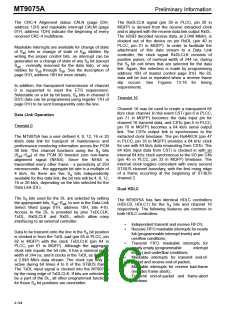
data. Channel alignment and bit numbering is
consistent with time slot alignment and bit
numbering. However, channels are numbered 1 to 30
and relate to time slots as per Table 3.
CRC-4 Multiframing
The primary purpose for CRC-4 multiframing is to
provide a verification of the current basic frame
alignment, although it can also be used for other
functions such as bit error rate estimation. The CRC-
4 multiframe consists of 16 basic frames numbered 0
to 15, and has a repetition rate of 16 frames X 125
microseconds/frame = 2 msec.
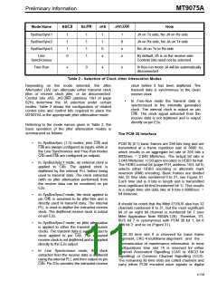
PCM 30
Timeslot
0
x
1 2 3...15
1 2 3...15
16 17 18 19...31
16 17 18...30
Voice/Data
Channels
x
CRC-4 multiframe alignment is based on the 001011
bit sequence, which appears in bit position one of the
first six NFASs of a CRC-4 multiframe.
Table 3 - Time Slot to Channel Relationship
Basic Frame Alignment
The CRC-4 multiframe is divided into two
submultiframes, numbered 1 and 2, which are each
eight basic frames or 2048 bits in length.
Time slot 0 of every basic frame is reserved for basic
frame alignment and contains either a Frame
Alignment Signal (FAS) or a Non-Frame Alignment
Signal (NFAS). FAS and NFAS occur in time slot zero
of consecutive basic frames as shown in Table 7. Bit
two is used to distinguish between FAS (bit two = 0)
and NFAS (bit two = 1).
The CRC-4 frame alignment verification functions as
follows. Initially, the CRC-4 operation must be
activated and CRC-4 multiframe alignment must be
achieved at both ends of the link. At the local end of
a link, all the bits of every transmit submultiframe are
passed through a CRC-4 polynomial (multiplied by
Basic frame alignment is initiated by a search for the
bit sequence 0011011 which appears in the last
seven bit positions of the FAS, see the Frame
Algorithm section. Bit position one of the FAS can be
either a CRC-4 remainder bit or an international
usage bit.
4
4
X then divided by X + X + 1), which generates a
four bit remainder. This remainder is inserted in bit
position one of the four FASs of the following
submultiframe before it is transmitted (see Table 7).
The submultiframe is then transmitted and, at the far
end, the same process occurs. That is, a CRC-4
remainder is generated for each received
submultiframe. These bits are compared with the bits
received in position one of the four FASs of the next
received submultiframe. This process takes place in
both directions of transmission.
Bits four to eight of the NFAS (i.e., S - S ) are
additional spare bits which may be used as follows:
a4
a8
•
•
•
S
to S may be used in specific point-to-point
a4 a8
applications (e.g. transcoder equipments
conforming to G.761).
S
may be used as a message-based data link
a4
for operations, maintenance and performance
monitoring.
When more than 914 CRC-4 errors (out of a possible
1000) are counted in a one second interval, the
framing algorithm will force a search for a new basic
frame alignment. See Frame Algorithm section for
more details.
S
to S are for national usage.
a8
a5
A maintenance channel or data link at 4,8,12,16,or
20 kHz for selected S bits is provided by the
a
MT9075A to implement these functions. Note that for
simplicity all S bits including Sa4 are collectively
called national bits throughout this document.
a
The result of the comparison of the received CRC-4
remainder with the locally generated remainder will
be transported to the far end by the E-bits.
Bit three (designated as “A”), the Remote Alarm
Indication (RAI), is used to indicate the near end
basic frame synchronization status to the far end of a
link. Under normal operation, the A (RAI) bit should
be set to 0, while in alarm condition, it is set to 1.
Therefore, if E = 0, a CRC-4 error was discovered in
1
a submultiframe 1 received at the far end; and if E =
2
0, a CRC-4 error was discovered in a submultiframe
2 received at the far end. No submultiframe
sequence numbers or re-transmission capabilities
are supported with layer 1 PCM 30 protocol. See
ITU-T G.704 and G.706 for more details on the
operation of CRC-4 and E-bits.
Bit position one of the NFAS can be either a CRC-4
multiframe alignment signal, an E-bit or an
international usage bit. Refer to an approvals
laboratory and national standards bodies for specific
requirements.
4-140

 MITEL [ MITEL NETWORKS CORPORATION ]