MT9075A
Preliminary Information
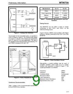
The receive LIU circuit requires a terminating
resistor of either 120Ω or 75Ω across the device side
of the receive1:1 transformer as shown in Figure 4.
The return loss of the receiver, complying with
G.703, is greater than:
Functional Description
MT9075A Line Interface Unit (LIU)
Receiver
•
•
•
12 dB from 51 kHz to 102 kHz;
18 dB from 102 kHz to 2048 kHz;
14 dB from 2048 kHz to 3072 kHz.
The receiver portion of the MT9075A LIU consists of
an input signal peak detector, an optional two-stage
equalizer, a smoothing filter, adaptive threshold
comparators, data and clock slicers, and a clock
extractor. Receive equalization gain can be set via
software control or it can be determined
automatically by the peak detectors.
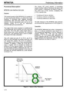
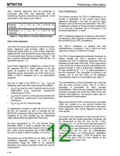
The jitter tolerance of the MT9075A clock extractor
circuit exceeds the requirements of G.823 (Figure 3).
Transmitter
The output of the receive equalizer is conditioned by
a smoothing filter and is passed on to the clock and
data slicer. The clock slicer output signal drives a
phase locked loop, which generates the extracted
clock (E2o). This extracted clock is used to sample
the output of the data comparator.
The MT9075A differential line driver is designed to
drive a 1:2 step-up transformer (see Figure 4). In
120 Ω twisted pair applications, a 0.68 uF capacitor is
required between the TTIP and the transmit
transformer. For 75 Ω coaxial cable applications, a
0.68 uF capacitor and two 2.2 Ω series resistors are
required between the transformer and the TTIP and
TRING output pins as shown in Figure 4.
The LOS output pin (pin 61 in PLCC, pin 57 in
MQFP) is user selectable, by setting control bit LOS/
LOF (page 02H, register 13H, bit 2), to indicate a
loss of signal or loss of basic frame synchronization
condition. In addition, a status bit, LLOS (bit 4 in
page 3, register 18H) is provided to indicate the
presence of a loss signal condition. The occurrence
of a loss signal condition is defined as per I.431, i.e.,
when the incoming signal amplitude is more than 20
dB below the nominal amplitude for a time duration
of at least 1 ms.
Peak to Peak
Jitter Amplitude
(log scale)
18UI
MT9075A
Tolerance
1.5UI
0.2UI
Jitter Frequency
(log scale)
1.667Hz
20Hz
2.4kHz 18kHz 100kHz
Figure 3 - Typical Jitter Tolerance
4-136

 MITEL [ MITEL NETWORKS CORPORATION ]