MT8931C
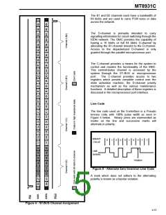
The C-channel bit mapping from the parallel port to
the ST-BUS is organized such that the most
significant bit is transmitted or received first.
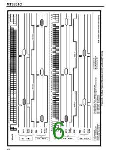
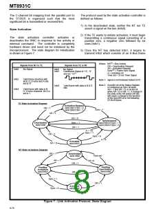
The protocol used by the state activation controller is
defined as follows:
1) In the deactivated state, neither the NT nor TE
assert a signal on the line (Info0).
State Activation
2) If the TE wants to initiate activation, it must begin
transmitting a continuous signal consisting of a
positive zero, a negative zero followed by six
ones (Info1).
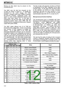
The state activation controller activates or
deactivates the SNIC in response to line activity or
external command. The controller is completely
hardware driven and need not be initialized by the
microprocessor. The state diagram for initialization
is shown in Figure 7.
3) Once the NT has detected Info1, it begins to
transmit Info2 which consists of an S-Bus frame
(2)
Where: BA = Bus Activity
Signals from NT to TE
Signals from TE to NT
DR = Deactivation Request
AR = Activation Request
Info0
Info2
Info4
No Signal
Info0
Info1
No Signal
(2)
Sync = Frame Sync Signal
Continuous Signal of +‘0’, -‘0’
(1)
A = Activation bit
Time out = 32 ms Timer Signal
and six ‘1’s
Valid frame structure with
all B, D, D-echo and A bits
set to ‘0’
Note 1: signal is not timebase locked to NT.
Note 2: Sync/BA bit of the Status Register
is configured as Sync bit when
AR = 1 and DR = 0, or as BA bit
when AR = 0 or DR = 1. A change in
the state of the AR and/or DR bits
will cause a change in the function
of the Sync/BA bit in the following
ST-BUS frame.
Info3
Valid frame with data in B & D
Bits
Valid frame with data in B,
D, D-echo channels. Bit A is
set to 1.
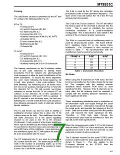
TE State Activation Diagram
DR = 1
Activation Request
send Info1 if BA = 0
send Info0 if BA = 1
Sync = 1
AR = 1
BA = 0
Sync = 1
DR = 1
Synchronized
send Info3 if Sync = 1
send Info0 if Sync = 0
Deactivated
send Info0
A = 1 &
Sync = 1
DR = 1
Sync = 0
A = 0
Activated
send Info3
BA = 0
NT State Activation Diagram
BA = 1
Deactivated
send Info0
Time out
BA =0
AR = 1
DR = 1
AR = 1
Pending
Deactivation
Send Info0
Pending
Activation
send Info2
Sync = 1
Sync = 0
DR = 1
Activated
send Info4
Figure 7 - Link Activation Protocol, State Diagram
9-78

 MITEL [ MITEL NETWORKS CORPORATION ]