MT8931C
After successfully completing a transmission, the
internal priority level is reduced from high to low.
The internal priority will only be increased once the
terminal count for the respective level of priority has
For an NT SNIC in fixed timing mode, the VCO and
Rx filters/peak detectors are disabled and the
threshold voltage is fixed. However, for a TE SNIC or
an NT SNIC (in adaptive timing mode), the VCO and
been achieved.
(e.g., if TE has high priority
Rx filters/peak detectors are enabled.
In this
internally and externally, it must count 8 consecutive
ones in the D-echo channel. Once this is achieved
and successful transmission has been completed,
the internal priority is reduced to a lower level (i.e.,
count = 9). This terminal will not return to the high
internal priority until 9 consecutive ones have been
monitored on the D-echo channel).
manner, the device can compensate for variable
round trip delays and line attenuation using a
threshold voltage set to a fixed percentage of the
pulse peak amplitude.
Another operation can be implemented using the
SNIC in the star configuration as shown in Figure 14.
This mode allows multiple NTs, with physically
independent S-Busses, to share a common input
source and transfer information down the S-Bus to all
TEs . All NT devices connected into the star will
receive the information transmitted by all TEs on all
branches of the star, exactly as if they were on the
same physical S-Bus. All NTs in the star
configuration must be operating in fixed timing mode.
Refer to the description of the star configuration in
the ST-BUS section.
Line Wiring Configuration
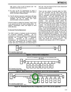
The MT8931C can interface to any of the three
wiring configurations which are specified by the
CCITT Recommendation I.430 and ANSI T1.605
(refer to Figures 8 to 10). These consist of a
point-to-point or one of the two point-to- multipoint
configurations (i.e., short passive bus or the
extended passive bus).
The selection of line
configurations is performed using the timing bit (B4
of NT Mode Control Register).
The SNIC has one last mode of operation called the
NT slave mode. This has the effect of operating the
SNIC in network termination mode (XTAL1/NT pin =
1) but having the frame structure and registers
description defined by the TE mode. This can be
used where multiple subscriber loops must carry a
fixed phase relation between each line. A typical
For the short passive bus, TE devices are connected
at random points along the cable. However, for the
extended passive bus all connection points are
grouped at the far end of the cable from the NT.
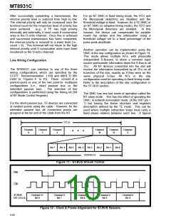
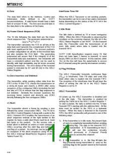
125 µs
Channel
0
Channel
1
Channel
2
Channel
30
Channel
31
Channel
0
• • •
Bit 7
Bit 6
Bit 5
Bit 4
Bit 3
Bit 2
Bit 1
Bit 0
(8/2048) ms
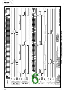
Figure 11 - ST-BUS Stream Format
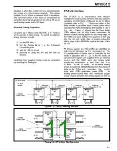
F0b
C4b
ST-BUS
BIT CELLS
Channel 31
Bit 0
Channel 0
Bit 7
Channel 0
Bit 6
Channel 0
Bit 5
Channel 0
Bit 4
Figure 12 - Clock & Frame Alignment for ST-BUS Streams
9-80

 MITEL [ MITEL NETWORKS CORPORATION ]