MT8931C
Both, one and two byte address recognition is
supported by the SNIC. A transparent mode allows
data to be passed directly to the D channel without
being packetized.
Functional Description
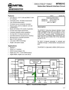
The MT8931C Subscriber Network Interface Circuit
(SNIC) is a multifunction transceiver providing a
complete interface to the S/T Reference Point as
specified in ETS 300-012, CCITT Recommendation
A block diagram of the MT8931C is shown in Figure
1. The SNIC has three interface ports: a 4-wire
CCITT compatible S/T interface (subscriber loop
interface), a 2048 kbit/s ST-BUS serial port, and a
general purpose parallel microprocessor port. This
8-bit parallel port is compatible with both Motorola or
Intel microprocessor bus signals and timing.
I.430 and ANSI T1.605.
Implementing both
point-to-point and point-to-multipoint voice/data
transmission, the SNIC may be used at either end of
the digital subscriber loop. A programmable digital
interface allows the MT8931C to be configured as a
Network Termination (NT) or as
Equipment (TE) device.
a
Terminal
The three major blocks of the MT8931C, consisting
of the system serial interface (ST-BUS), HDLC
transceiver, and the digital subscriber loop interface
(S-interface) are interconnected by high speed data
The SNIC supports 192 kbit/s (2B+D + overhead) full
duplex data transmission on a 4-wire balanced
transmission line. Transmission capability for both B
and D channels, as well as related timing and
synchronization functions, are provided on chip. The
signalling capability and procedures necessary to
enable customer terminals (TEs) to be activated and
deactivated, form part of the MT8931C’s
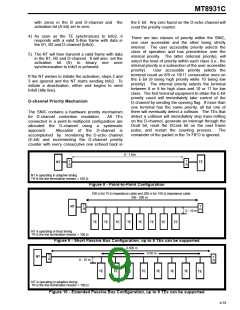
functionality. The SNIC handles D-channel resource
allocation and prioritization for access contention
resolution and signalling requirements in passive bus
line configurations. Control and status information
allows implementation of mainten-ance functions
and monitoring of the device and the subscriber loop.
busses.
Data sent to and received from the
S-interface port (B1, B2 and D channels) can be
accessed from either the parallel microprocessor
port or the serial ST-BUS port. This is also true for
SNIC control and status information (C-channel).
Depacketized D-channel information to and from the
HDLC section can only be accessed through the
parallel microprocessor port.
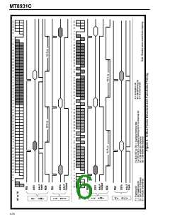
S-Bus Interface
The S-Bus is a four wire, full duplex, time division
multiplexed transmission facility which exchanges
information at 192 kbit/s rate including two 64 kbit/s
PCM voice or data channels, a 16 kbit/s signalling
channel and 48 kbit/s for synchronization and
overhead. The relative position of these channels
with respect to the ST-BUS is shown in Figures 4
and 5.
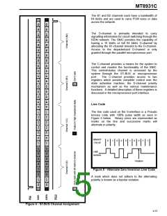
An HDLC transceiver is included on the SNIC for link
access protocol handling via the D-channel.
Depacketized data is passed to and from the
transceiver via the microprocessor port. Two 19 byte
deep FIFOs, one for transmit and one for receive, are
provided to buffer the data. The HDLC block can be
set up to transmit or receive to/from either the
S-interface port or the ST-BUS port. Further, the
transmit destination and receive source can be
independently selected, e.g., transmit to S-interface
while receiving from ST-BUS. The transmit and
receive paths can be separately enabled or disabled.
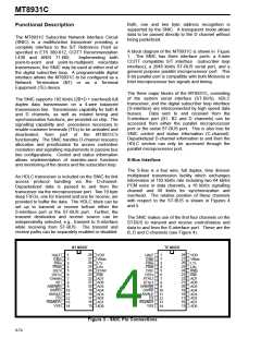
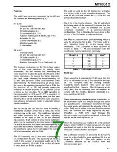
The SNIC makes use of the first four channels on the
ST-BUS to transmit and receive control/status and
data to and from the S-interface port. These are the
B, D and C-channels (see Figure 4).
NT MODE
TE MODE
28
27
26
25
24
23
22
21
20
19
18
17
16
15
28
27
26
25
24
23
22
21
20
19
18
17
16
15
1
2
3
4
5
6
7
8
1
2
3
4
5
6
7
8
HALF
C4bi
F0bi
F0od
DSTi
VDD
VBias
LTx
LRx
STAR
Rsti
AD7
AD6
AD5
AD4
AD3
AD2
AD1
AD0
HALF
C4bo
F0bo
F0od
DSTi
VDD
VBias
LTx
LRx
Rsto
Rsti
AD7
AD6
AD5
AD4
AD3
AD2
AD1
AD0
DSTo
Cmode
NT
R/W/WR
DS/RD
AS/ALE
CS
DSTo
XTAL2
XTAL1
R/W/WR
DS/RD
AS/ALE
CS
9
9
10
11
12
13
14
10
11
12
13
14
IRQ/NDA
VSS
IRQ/NDA
VSS
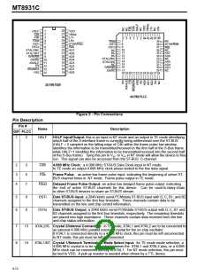
Figure 3 - SNIC Pin Connections
9-74

 MITEL [ MITEL NETWORKS CORPORATION ]