MT8931C
filtering out jitter which may be present on the
received line port.
The flow of data in the direction of S-Bus to ST-BUS
is transparent to the SNIC, regardless of the state
machine status. On the other hand, the flow of data
in the direction of ST-BUS to S-Bus becomes
transparent only after the state machine is in the
active state (IS0, IS1=1,1), in case of an NT, or in the
synchronization state (IS0, IS1=1), in case of a TE.
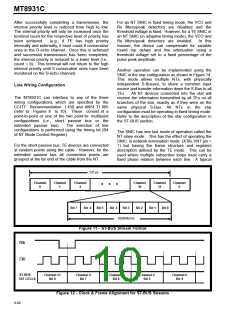
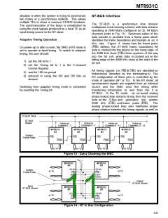
The SNIC uses the first four channels on the
ST-BUS (as shown in Figure 4). To simplify the
distribution of the serial stream, the SNIC
provides a delayed frame pulse (F0od) to eliminate
the need for a channel assignment circuit. This
signal is used to drive subsequent devices in the
Microprocessor/Control Interface
daisy chain (refer Figure 13).
In this type of
arrangement, only the first SNIC in the chain will
receive the system frame pulse (F0b) with the
following devices receiving its predecessor’s delayed
output frame pulse (F0od).
The microprocessor port is compatible with either
Motorola or Intel multiplexed bus signals and timing.
The MOTEL
Compatible bus) uses the level of the DS/RD pin
at the rising edge of AS/ALE to select the
circuit
(MOtorola
and
InTEL
appropriate bus timing. If DS/RD is low at the
rising edge of AS/ALE (refer to Figure 26) then
Motorola bus timing is selected. Conversely, if DS/
RD is high at the rising edge of AS/ALE (refer to
Figures 24 & 25), then Intel bus timing is selected.
This has the effect of redefining the microprocessor
port transparently to the user.
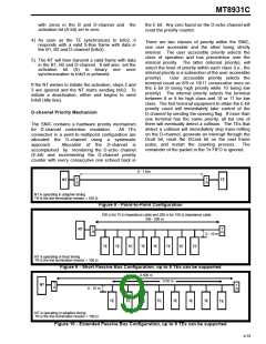
The SNIC makes efficient use of its TDM bus
through the Star configuration. It does so by sharing
four common ST-BUS channels to multiple NT
devices. Up to eight SNICs in NT mode with
physically independent S-Busses can be connected
in parallel to realize a star configuration (as shown in
Figure 14). All devices connected into the star will
carry the same input, thus information is sent to all
TEs simultaneously. The 2B+D data received from
every TE is transmitted to all NTs through the STAR
pin. Consequently, all the DSTo streams will carry
identical 2B+D data reflecting what is being
transmitted by the various TEs.
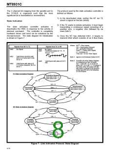
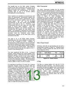
The user has the option of writing to the C-channel
Control or Diagnostic Register through the parallel
port interface or through the C-channel on DSTi. Bit
0 of the Master Control Register provides this option.
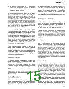
Address Lines
Write
Master Control Register
Read
A4 A3 A2 A1 A0
0
0
0
0
0
0
0
0
0
0
1
1
0
0
0
0
0
0
0
0
0
0
0
0
0
0
0
0
1
1
0
0
1
1
1
1
1
1
1
1
0
0
0
0
1
1
1
1
0
0
0
0
0
0
0
0
1
1
1
1
0
0
1
1
0
0
1
1
0
0
0
1
0
0
1
1
0
0
1
1
0
1
0
1
0
1
0
1
0
1
0
0
0
1
0
1
0
1
0
1
verify
A
S
Y
N
C
ST-BUS Control Register
HDLC Control Register 1
HDLC Control Register 2
HDLC Interrupt Mask Register
HDLC Tx FIFO
verify
verify
HDLC Status Register
HDLC Interrupt Status Register
HDLC Rx FIFO
verify
HDLC Address Byte #1 Register
HDLC Address Byte #2 Register
C-channel Control Register
verify
C-channel Status Register
Not Available
Control Register 1
Not Available
Master Status Register
DSTi C-channel
DSTo C-channel
S-Bus Tx D-channel
DSTo D-channel
S
Y
N
C
DSTi D-channel
S-Bus Rx D-channel
DSTi B1-channel
S-Bus Tx B1-channel
DSTo B1-channel
S-Bus Rx B1-channel
DSTi B2-channel
S-Bus Tx B2-channel
DSTo B2-channel
S-Bus Rx B2-channel
Table 2. SNIC Address Map
9-82

 MITEL [ MITEL NETWORKS CORPORATION ]