MT8931C
Framing
The A-bit is used by the NT during line activation
procedures (refer to state activation diagrams). The
state of the A-bit will advise the TE if the NT has
achieved synchronization.
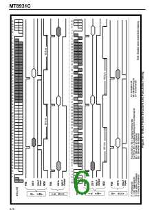
The valid frame structure transmitted by the NT and
TE contains the following (refer Fig. 6):
The E-bit is the D-echo channel. The NT will reflect
the binary value of the received D-channel into the
NT to TE:
- Framing bit (F)
E-bits.
This is used to establish the access
point-to-multipoint
- B1 and B2 channels (B1,B2)
- DC balancing bits (L)
- D-channel bits (D0, D1)
- Auxiliary framing and N bit (Fa, N), N=Fa
- Activation bit (A)
- D-echo channel bits (E)
- Multiframing bit (M)
- S-channel bit
contention resolution in
a
configuration. This is described in more detail in the
section of the D-channel priority mechanism.
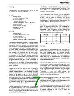
The M-bit is a second level of multiframing which is
used for structuring the Q-bits. The frame with M-
bit=1 identifies frame #1 in the twenty frame
multiframe. The Q-channel is then received as
shown in Table 1. All synchronization with the
multiframes must be performed externally.
TE to NT:
- Framing bit (F)
- B1 and B2 channels (B1, B2)
- DC balancing bits (L)
- D-channel bits (D0, D1)
- Auxiliary framing bit (Fa) or Q-channel bit
FRAME #
Q-BIT
M-BIT
1
6
Q1
Q2
Q3
Q4
1
0
0
0
11
16
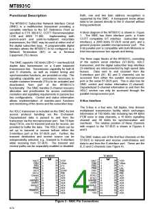
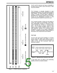
The framing mechanism on the S-interface makes
use of line code violations to identify frame
boundaries. The F-bit violates the alternating line
code sequence to allow for quick identification of the
frame boundaries. To secure the frame alignment,
the next mark following the frame balancing bit
(L) will also produce a line code violation. If the
data following the balancing bit is all binary ones,
the zero in the auxiliary framing bit (Fa) or N-bit (for
the direction NT to TE) will provide successive
violations to ensure that the 14 bit criterion (13 bit
criterion in the direction TE to NT) specified in
Recommendations I.430 and T1.605 is satisfied. If
the B1-channel is not all binary ones, the first zero
following the L-bit will violate the line code sequence,
thus allowing subsequent marks to alternate without
bipolar violations.
Table 1. Q-channel Allocation
Bit Order
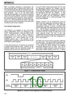
When using the B-channels for PCM voice, the first
bit to be transmitted on the S-Bus should be the sign
bit. This complies with the existing telecom
standards which transmit PCM voice as most
significant bit first. However, if the B-channels are to
carry data, the bit ordering must be reversed to
comply with the existing datacom standards (i.e.,
least significant bit first).
These contradicting standards place a restriction on
all information input and output through the serial
and parallel ports. Information transferred through
the serial ports, will maintain the integrity of the bit
order. Data sent to either serial port from the parallel
port, will transmit the least significant bit first.
The Fa and N bits can also be used to identify a
multiframe structure (when this is done, the 14 bit
criterion may not be met). This multiframe structure
will make provisions for a low speed signalling
channel to be used in the TE to NT direction
(Q-channel). It will consist of a five frame multiframe
which can be identified by the binary inversion of the
Fa and N-bit on the first frame and consequently on
every fifth frame of the multiframe. Upon detection of
the multiframe signal, the TE will replace the next Fa-
bit to be transmitted with the Q-bit.
Therefore,
a
PCM byte input through the
microprocessor port must be reordered to have the
sign bit as the least significant bit.
When the microprocessor reads D, B1 or B2 channel
data of either ST-BUS or S-bus serial port, the least
significant bit read is the first bit received on that
particular channel of either serial port.
The D-channel received on the serial ST-BUS ports
must be ordered with the least significant bit first as
The DC balancing bits (L) are used to remove any
DC content from the line. The balancing bit will be a
mark if the number of preceding marks up to the
previous balancing bit is odd. If the number of marks
is even, the L-bit will be a space.
shown in Figure 4.
This also applies to the
D-channel directed to the ST-BUS from the
microprocessor port.
9-77

 MITEL [ MITEL NETWORKS CORPORATION ]