MT8931C
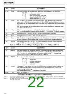
BIT
NAME
DESCRIPTION
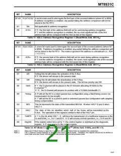
B7-B6
Loop
The status of these two bits determine which type of loopback is to be performed:
B7 - B6
0 - 0
0 - 1
1 - 0
1 - 1
- no loopback active
- near end loopback LTx to LRx
- digital loopback DSTi to DSTo
- remote loopback LRx to LTx
B5
FSync
If ’1’, the device will maintain frame synchronization even after losing the frame sync
sequence (i.e., if the device is transmitting INFO2 or INFO4 and this bit is set, the same
INFO signal will still be transmitted even if the frame sync sequence in the received signal
is lost).
If ’0’, synchronization will be declared when three consecutive framing sequences have
been detected without error.
B4
FLv
If ’1’, the frame sync sequence will violate the bipolar violation encoding rule.
If ’0’, the framing pattern resumes normal operation, i.e., Framing bit is a bipolar violation.
B3
B2
B1
Idle
Setting this bit to ’1’ will force an all 1s signal to be transmitted on the line.
Setting this bit to ’1’ will force all D-echo bits (E) to zero.
Echo
Slave
If ’1’, the device will operate in a NT slave mode. This allows the device to be used at the
terminal equipment end of the line while receiving its clocks from an external source.
B0
RegSel
If the register select bit is set to ’1’, the control register is redefined as the diagnostic
register. A ’0’ gives access to the control register.
Table 14. NT Mode C-channel Diagnostic Register (Write Add. 01000B and B0 = 1)
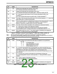
BIT
NAME
DESCRIPTION
B7
Sync/BA
This bit is set when the device has achieved frame synchronization while the activation
request is asserted (DR = 0 and AR = 1). If there is a deactivation request or AR is low
(DR = 1 or AR = 0), this bit indicates the presence of bus activity . A bus activity
(1)
identifies the reception of INFO frames (INFO1 or INFO3).
B6-B5
IS0-IS1
Binary encoded state sequence.
IS0 - IS1
0 -
0 -
1 -
1 -
0
1
0
1
- deactivated
- pending deactivation
- pending activation
- activated
B4
RxMCH
NA
Following a ‘0’ input at the HALF pin or HALF bit in the C-channel Control Register, the
state of this bit reflects the received maintenance Q-channel (received in the Fa bit
position during multiframing).
This bit will always read ‘1’ if multiframing is not used.
B3-B0
These bits will read ’1’.
(2)
Table 15. NT Mode Status Register (Read Add. 01001B)
Note 1:
Note 2:
Bus activity is set when three zeros are received in a time period equivalent to 48 bits or 250µs. It is reset when 128
consecutive ones are received.
The Status Register is updated internally once every ST-BUS frame. Therefore, more than one read access per frame will
return the same value.
9-92

 MITEL [ MITEL NETWORKS CORPORATION ]