MT8931C
BIT
NAME
DESCRIPTION
(3)
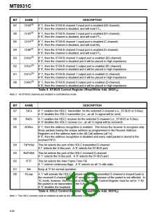
B7
CH3i
If ’1’, then the ST-BUS channel 3 input port is enabled (B2-channel).
If ’0’, then the channel is disabled, and will read FFH.
(3)
B6
B5
B4
B3
B2
B1
B0
CH2i
If ’1’, then the ST-BUS channel 2 input port is enabled (B1-channel).
If ’0’, then the channel is disabled, and will read FFH.
(3)
CH1i
If ’1’, then the ST-BUS channel 1 input port is enabled (C-channel).
If ’0’, then the channel is disabled, and will read 00H.
(3)
CH0i
If ’1’, then the ST-BUS channel 0 input port is enabled (D-channel).
If ’0’, then the channel is disabled, and will read FFH.
(3)
CH3o
If ’1’, then the ST-BUS channel 3 output port is enabled (B2-channel).
If ’0’, then the channel is disabled and it will be placed in High impedance.
(3)
CH2o
If ’1’, then the ST-BUS channel 2 output port is enabled (B1-channel).
If ’0’, then the channel is disabled and it will be placed in High impedance.
(3)
CH1o
If ’1’, then the ST-BUS channel 1 output port is enabled (C-channel).
If ’0’, then the channel is disabled and it will be placed in High impedance
(3)
CH0o
If ’1’, then the ST-BUS channel 0 output port is enabled (D-channel).
If ’0’, then the channel is disabled and it will be placed in High impedance.
Table 5. ST-BUS Control Register (Read/Write Add. 00001B)
Note 3: All ST-BUS channels are enabled in controllerless mode.
BIT
NAME
DESCRIPTION
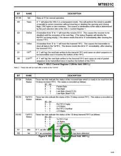
B7
TxEn
A ’1’ enables the HDLC transmitter for the selected D-channel (i.e., ST-BUS or S-Bus).
A ’0’ disables the HDLC transmitter (i.e., an all 1s signal will be sent).
B6
B5
RxEn
A ’1’ enables the HDLC receiver for the selected D-channel (i.e., ST-BUS or S-Bus).
A ’0’ disables the HDLC receiver (i.e., an all 1s signal will be received).
ADRec
If ’1’, then the address recognition is enabled. This forces the receiver to recognize only
those packets having the unique address as programmed in the Receive Address
Registers or if the address byte is the All-Call address (all 1s).
If ’0’, then the address recognition is disabled and every valid packet is stored in the
received FIFO.
B4
B3
B2
TxPrtSel This bit selects the port of the HDLC transmitted D-channel.
A’1’ selects the S-Bus port. A ’0’ selects the ST-BUS port.
RxPrtSel This bit selects the port of the HDLC received D-channel.
A ’1’ selects the S-Bus port. A ’0’ selects the ST-BUS port.
IFTF
This bit selects the Inter Frame Time Fill.
A ’1’ selects continuous flags. A ’0’ selects an all 1’s idle state.
B1
B0
NA
Keep at ’0’ for normal operation.
HLoop
A ’1’ will activate the HDLC loopback where the transmitted D-channel is looped back to
(1)
the received D-channel . In NT mode, the transmission of the packet is not affected. In
TE mode, however, the DReq bit of the C-channel Control Register must be set to ‘1’ for
the packet to be transmitted to the S-Bus.
A ’0’ disables the loopback.
Table 6. HDLC Control Register 1 (Read/Write Add. 00010B)
Note 1: The HDLC receiver must be enabled as well as the designated channel.
9-88

 MITEL [ MITEL NETWORKS CORPORATION ]