MT8931C
BIT
NAME
DESCRIPTION
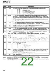
B7
Sync/BA
This bit is set if the device has achieved frame synchronization while the activation
request is asserted (DR = 0 and AR = 1). If there is a deactivation request or that AR is
low (DR = 1 or AR = 0), this pin indicates the presence of bus activity . A bus activity
(1)
identifies the reception of INFO frames (INFO2 or INFO4).
B6-B5
IS0-IS1
Binary encoded state sequence.
IS0 - IS1
0 -
0 -
1 -
1 -
0
1
0
1
- deactivated
- synchronized
- activation request
- activated
B4
B3
M/S
This bit respresents the state of the received M/S-bit. M when HALF=0 and S when
HALF=1
HALF
The state of this bit identifies which half of the S-Bus frame is currently being output on the
ST-BUS.
B2
B1
RxMFR
Priority
A ’1’ when HALF=0 indicates that the multiframe pattern on Fa and N has been detected.
The status of this bit indicates the internal priority of the device within the designated
priority class. If 1, then it has high priority within the priority class designated in B4 of
control register. If 0, then it has low priority within the priority class designated in B4 of
control register.
B0
DCack
A ’1’ indicates that the device has gained access to the D-channel and has transmitted an
opening flag. This bit is reset to ‘0’ when the closing flag of the last packet in the TxFIFO
is transmitted and the internal priority is reduced from high to low. A collision during
transmission will also reset this bit back to ‘0’.
(2)
Table 18. TE Mode Status Register (Read Add. 01001B)
Note 1:
Note 2:
Bus activity is set when three zeros are received in a time period equivalent to 48 bits or 250µs. It is reset when 128
consecutive ones are received.
The Status Register is updated internally once every ST-BUS frame. Therefore, more than one read access per frame will
return the same value.
BIT
NAME
DESCRIPTION
B7-B2
B1*
NA
Not available.
INFO1
In TE mode, this bit is set to ‘1’ only when the device is transmitting INFO1.
Not available in NT mode.
B0*
INFO0
In NT or TE mode, this bit is set to ‘1’ only when the device is transmitting INFO0.
Table 19. Master Status Register (Read Add. 10010B)
* These two bits can be used along with status bits IS0 and IS1 to distinguish between states F6/F8 and F4/F5 of the device’s state machine in
TE mode. Please refer to “State Machine” section of Application Note MSAN-141 for further details.
9-94

 MITEL [ MITEL NETWORKS CORPORATION ]