MT8931C
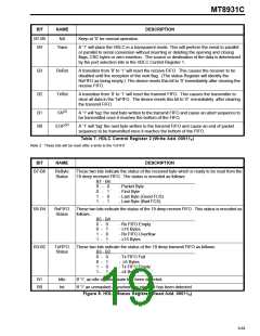
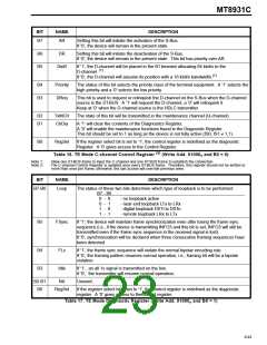
BIT
NAME
DESCRIPTION
B7-B5
B4
NA
Keep at ’0’ for normal operation.
Trans
A ’1’ will place the HDLC in a transparent mode. This will perform the serial to parallel
or parallel to serial conversion without inserting or deleting the opening and closing
flags, CRC bytes or zero insertion. The source or destination of the data is determined
by the port selection bits in the HDLC Control Register 1.
B3
B2
RxRst
TxRst
A transition from ‘0’ to ’1’ will reset the receive FIFO. This causes the receiver to be
disabled until the reception of the next flag. (The status Register will identify the
RxFIFO as being empty.) The device resets this bit to ‘0’ immediately after clearing the
receive FIFO.
A transition from ‘0’ to ’1’ will reset the transmit FIFO. This causes the transmitter to
clear all data in the TxFIFO. The device resets this bit to ‘0’ immediately after clearing
the transmit FIFO.
(2)
B1
B0
FA
A ’1’ will ’tag’ the next byte written to the transmit FIFO and cause an abort sequence to
be transmitted once it reaches the bottom of the FIFO.
(2)
EOP
A ’1’ will ’tag’ the next byte written to the transmit FIFO and cause an end of packet
sequence to be transmitted once it reaches the bottom of the FIFO.
Table 7. HDLC Control Register 2 (Write Add. 00011B)
Note 2: These bits will be reset after a write to the TxFIFO
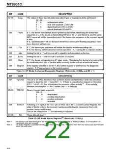
BIT
NAME
DESCRIPTION
B7-B6
RxByte
Status
These two bits indicate the status of the received byte which is ready to be read from the
19 deep received FIFO. The status is encoded as follows:
B7 - B6
0 - 0
0 - 1
1 - 0
1 - 1
- Packet Byte
- First Byte
- Last Byte (Good FCS)
- Last Byte (Bad FCS)
B5-B4
B3-B2
RxFIFO
Status
These two bits indicate the status of the 19 deep receive FIFO. This status is encoded as
follows:
B5 - B4
0 - 0
0 - 1
1 - 0
1 - 1
- Rx FIFO Empty
- ≤14 Bytes
- Rx FIFO Overflow
- ≥15 Bytes
TxFIFO
Status
These two bits indicate the status of the 19 deep transmit FIFO as follows:
B3 - B2
0 - 0
0 - 1
1 - 0
- Tx FIFO Full
- ≥5 Bytes
- Tx FIFO Empty
- ≤4 Bytes
1 -
1
B1
B0
Idle
Int
If ’1’, an idle channel state has been detected.
If ’1’ an unmasked asynchronous interrupt has been detected.
Figure 8. HDLC Status Register (Read Add. 00011B)
9-89

 MITEL [ MITEL NETWORKS CORPORATION ]